


Services on Demand
Journal

Article
 English (pdf)
 Article in xml format
 Article references
 Send this article by e-mail
Indicators
Related links
-
 Cited by Google
 -
 Similars in Google
Share

 Permalink
Journal of the Southern African Institute of Mining and Metallurgy
On-line version ISSN 2411-9717Print version ISSN 2225-6253
J. S. Afr. Inst. Min. Metall. vol.125 n.8 Johannesburg Aug. 2025
https://doi.org/10.17159/2411-9717/3606/2025
SLOPE STABILITY THEMED EDITION
Slope stability evaluation of Gneiss rock slopes using slope mass rating (SMR) and QSlope
E. KalhanI; C. KincalII
IDokuz Eylul University, Graduate School of Natural and Applied Sciences, Geological Engineering Department, Turkey. http://orcid.org/0000-0001-6385-4968
IIGeological Engineering Department, Engineering Faculty, Dokuz Eylul University, Tinaztepe Campus, Turkey. http://orcid.org/0000-0002-3279-4170
ABSTRACT
One of the biggest problems in open pit mining is slope stability. The avoidance of slope stability problems depends on a comprehensive assessment of environmental and operational factors such as geology, climate, and mining activities. In the light of these considerations, slope geometries should be determined in accordance with engineering principles. In this research, the slope stability of rock slopes in a mine opened in a gneiss geological unit has been studied. Production activities were ceased in 2019 due to the slope movements in the eastern part of the quarry. In order to safely continue the production, field works were primarily carried out. To assess slope stability, detailed discontinuity surveys were carried out on bench faces. Subsequently, kinematic and numerical analyses were employed to identify geometries that are expected to maintain stability under the prevailing geological structures and environmental constraints. Engineering geological studies such as scanline measurements in steps and investigation of potential failure mechanisms by kinematic analysis technique were carried out. Small module reactor and Q-slope rock mass classification systems were used to evaluate slope stability. Based on these classification systems potential unstable rock slopes were identified and thematic maps were created using geographic information systems. The most suitable slope geometries are suggested for these slopes. In addition, the improvement methods suggested by the rock mass classification systems were proposed for these slopes.
Keywords: gneiss, Q-slope, slope mass rating (SMR), rock mass classification systems, slope stability, open pit mine
Introduction
Although there are many definitions of slope it can be generally defined as "the mass that makes a certain angle with the Earth's face" (Cernica, 1995; Das, 1994). Slope failures usually cause great loss of property and lives. Therefore, engineers have to determine and evaluate the stability of slopes (Coduto, 1999).
Mass movements dominantly occur as a result of gravitational forces acting on slope. However, there may be one or more reasons that accelerate the occurrence of these movements. These can be divided into internal and external causes. External causes include "excavations on the toe of the slope changing the angle of the slope, removing the overburden of the slope and facilitating the entry of surface waters into the slope", while internal causes include "increase in pore water pressure (u), decrease in cohesion of the slope material and decrease in the internal friction angle" (Kiliç, 2005).
For safe slope design geological conditions should be considered. Therefore, different slope designs around the mine may be required. It is the determination of the maximum slope height and slope angle planned for rock slopes. In the first stage of design, there is a balance between slope stability and economy. It means that the volume of rock required to be excavated is less and steeper slopes have a lower cost than slopes with less slopes (Hoek, Bray, 2004).
Rock mass classification has become extremely important in engineering projects. It is a useful tool as it saves time and provides detailed information. For this purpose, Terzaghi (1946) presented the first empirical classification system developed. As a result of this system and subsequent studies, these empirical systems have been continuously improved by Deere et al., (1966, 1970), who developed a classification system based on the principle of evaluating the main discontinuity features in the rock mass, known as the rock quality designation (RQD), and improved this system in their forward studies (Deere, 1989). Rock mass rating (RMR) and Q-system can be considered as the backbone of rock mass classification systems (Barton et al., 1974; Bieniawski, 1973; Tomás et al., 2012; Chen et al., 2017). However, there are some limitations in using these classification systems for slopes. Both classification systems have many shortcomings as they only consider the rock mass and related geological factors. In general, both systems make a classification by evaluating only geological conditions (Pantelidis, 2009; Paul et al., 2012; Jhanwar, 2012). The slope mass rating (SMR) classification is based on the RMR system and takes into account both the geological conditions in the rock mass and the geometrical relationship between the slope and discontinuities. Romana (1985) emphasised that besides these relationships, the method of production is also important in slope stability and should be taken into account. If kinematic failure is observed on a slope, SMR can be applied on these slopes (Basahel, Mitri, 2017). Many studies have been carried out for this purpose. Riquelme (2016) used this system in different scenarios. These studies show that SMR provides highly reliable results in predicting failure. However, he stated the main advantages of using the SMR index calculation technique and stated that this approach can be used on a large scale in engineering projects that may develop in the coming years (Riquelme, Tomás, 2016). Myat and Aung (2022) studied the area between Kywedatson and Wetphyuye, in the Mandalay Region of Myanmar, which consists of different sedimentary, igneous and metamorphic rocks. Based on the SMR results, they divided the road slopes into (a) very low hazard zone, (b) low hazard zone, (c) medium hazard zone and, (d) high hazard zone in terms of landslides. They identified 29 rockfalls out of 54 areas and predicted that the failures can be reduced by the improvement methods proposed according to the SMR system.
Siddique (2015) conducted studies in the Himalayan region, which is a very active region, to determine safe areas and to determine their vulnerability to sliding. According to the results of the study, it was stated that the SMR values, which vary in different ranges, are in the stable class and/or some block failures may occur. Ietto (2018) conducted a study to reveal the engineering characteristics of the weathering profiles of granitoid rocks located on the southern edge of the Capo Vaticano cape, in the south-central part of the Calabria-Peloritani Arc. According to the SMR system, working slopes are classified as completely unstable, unstable, partially stable, and stable. By determining plane failure, toppling failure, and wedge type failure in the examined slopes, the comparison between the potential and actual stability conditions of the examined slopes clearly demonstrated a good agreement. Sandria (2023) applied SMR at the inlet and outlet of the Dolok Dam diversion tunnel and successfully identified slope failures and/or slides. Jordá-Bordehore (2017) used slopes found in mining and construction activities for the Q-slope classification. He determined the stability of slopes below 30 m, such as slate, granite, and limestone, located in the Guadarrama mountain range north of Madrid, Spain. It has been shown that the obtained results can be used in different engineering projects and have been successfully applied in back analysis. Ravoshti (2018) used the Q-slope classification system to investigate the stability of jointed rock slopes in the Bonab-Malekan highway project. Along the route, 10 different slopes were determined for slope geometries to be used in future projects. According to the results of the study conducted on the slopes examined based on the Q-slope principle, 5 slopes were determined as partially unstable, 4 slopes as stable and 1 slope as unstable. Q-slope, another classification system, was tried to establish a correlational relationship between Q-slope and the stability of the slopes, as a result of the studies carried out by Azarafza (2020) on some sedimentary rock slopes in the Iranian region. For this purpose, supervised learning models were used to obtain a correlation with the Q-slope studies for 200 slopes representing the tectonic structures of Iran in 10 regions such as Zagros, Alborz, and the Southeast Mountains. According to his results, he showed that the distribution for the instability class is limited to two linear cases called Line U (upper limit) and Line B (lower limit).
In this study, slopes of an open pit mine opened in gneiss is considered for the reasons stated in the aforementioned. There are many different mining enterprises, large and small, in this area of study and slope movements are common in this area. Field investigations, engineering geological works, and rock slope stability assessments were carried out within the scope of this study in order to stabilise the rock slopes opened in gneiss and to continue operations. The stability of the slopes was determined with the measurements made in the summer months of 2020. With the help of these studies, the determination of unstable slopes and the improvement and/or reinforcement processes of these slopes were determined in order to continue the production in a safe and efficient way. However, the steepest slope angles that can remain stable without any reinforcement and improvement are revealed. In addition, a digitising process was carried out using geographic information systems in order to evaluate these slopes, so as to identify the slopes that may experience failure and to better understand the classification systems that were used.
Geology
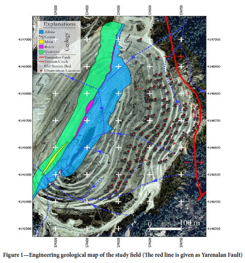
The study area is located in the Menderes Massif, which constitutes one of the main tectonic zones of Anatolides that crop out in Western Anatolia (Graciansky, 1965). There are eighteen albite open pits of different sizes in this region. The studied mine is one of the most famous albite mining sites in the region (Kincal, 2014). Leucocratic orthogneisses rich in terms of tourmaline were exposed in the study area. Two types of tourmaline-rich leucocratic orthogneisses were detected in the study area. The first group consists of orthogneisses derived from granoblastic textured coarse granites. The foliation planes of these rocks are defined by the parallel sequence of muscovites. This condition type consists of medium-grained, albite-rich leucocratic orthogneisses (Candan et al., 2005). All of the geological units in the open pit albite mine have been deformed by a shear zone. The Na-feldspar ore-bearing zone with mineralogical composition was developed along the shear zone. The dip directions of foliation planes in orthogneisses are almost perpendicular to this zone. Orthogneisses are characterised by their massive structures. It is seen that the mine site contains gneiss as ore body and wall rock (Figure 1). The direction of the ore deposit is N27E/55-60SE with an approximate length of 660 m developing along the shear zone in the mine. Metaquartzite and rutile lenses are observed. These lenses tend in the NE-SW direction.
Engineering geology
Rock slopes often experience failure along existing geological structures. Therefore, most slope problems require consideration of geometric relationships between discontinuity planes, slope, and related force vectors. One of the most important requirements for rock slopes is to determine the correct failure mechanism (Bell, 1992). Within the scope of this study, scan-line works proposed by ISRM (2007) was conducted at 119 different observation points in the eastern part of the open pit mine opened in gneisses (Figure 1).
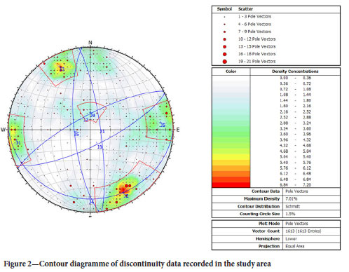
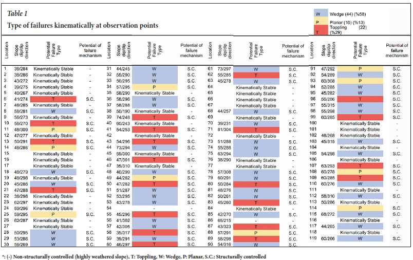
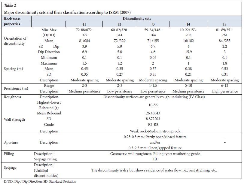
A total of 1613 discontinuity measurements were recorded from these observation points and the data (such as orientation of discontinuity spacing, persistence, roughness, etc.) were evaluated according to ISRM (2007) standards. The orientations of the discontinuity planes were transferred to the stereographic projection with Dips 7.016 software (RocScience, 2019) and the type of failures at each observation point was evaluated kinematically and expressed as a percentage in Table 1. In addition, the major discontinuity sets in the open pit mine slopes were determined by using the pole concentration points of all discontinuities taken from the eastern part of the mine (Figure 2). In addition, the classes and properties of the dominant discontinuity sets recommended by ISRM (2007) are given in Table 2.
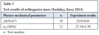
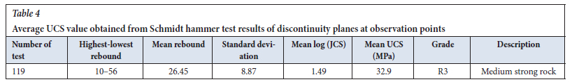
In addition, the Schmidt hammer test was conducted to measure the uniaxial compressive strength (UCS) of discontinuity planes proposed by Barton and Choubey (1973). Experiments were carried out with an L-type Schmidt hammer at a total of 119 different points. As a result of the laboratory studies conducted by Kadakçi and Koca (2014) belonging to the same region, the unit weight values of orthogneisses were used (Table 3). UCS values were calculated by using the following Equation 1 suggested by Barton and Choubey (1977). Orthogneiss rock slopes were determined to be 'moderately strong' according to the Anon (1977) classification (Table 4).

Where:
JCS: Strength of the discontinuity surface (MPa)
γ: Unit volume weight (kN/m3)
R: Schmidt rebound value.
Slope stability assessments
Rock mass classifications form the backbone of the experimental design approach and are widely used in rock engineering (Singh, Goel, 2011). Rock mass classification systems are very helpful in the front-end of a project where very little data is available (Hoek, 2007). RMR and Q-system are the most widely used among rock mass classification systems in rock mechanics and engineering by engineering geologists, mining geologists, and consultants (Morales, 2017). However, it is almost impossible to apply the correction factor for slopes due to the wide range of correction factors and the lack of definition factors (Romana et al., 2015). However, Q-system is also not applicable for slopes. Due to this deficiency, the Q-slope system for slopes was developed by Barton and Bar (2015). In this study, two of the rock mass classification systems discussed in the aforementioned were used to evaluate the slope stability of the open pit mine. These are SMR and Q-slope systems. In order to calculate the %RQD used as input parameter for both SMR and Q-slope classification system, Equation 2 proposed by Priest and Hudson (1976) was used.

Where λ is the number of fractures in a metre. For the interpretation and evaluation of rock mass classification systems, the geographic information system software was used, and the rock classification rating was digitised by IDW method.
In rock mass classification systems, which are carried out on this research, parameters such as slope geometry, attribute of discontinuities that causes failure, discontinuity spacing, roughness, friction angle, and filling material were taken into account for analyses.
Slope mass rating (SMR)
SMR is a geotechnical classification system developed by Romana (1985) for rock slopes and obtained from basic RMR. It is calculated by adding a few adjustment factors to the basic RMR system. These adjustment factors are directly related to the relationship between the joints in the rock slope and the slope geometry. However, it also takes into account the excavation or blasting method. The SMR score calculated by subtracting from the RMR system is obtained with the given Equation 3.

Where rock mass rating (RMR) is a system developed by Bieniawski (1973, 1989) to evaluate the quality of rock masses in engineering projects. The RMR system is derived from the rock mass classification framework introduced by Bieniawski (1989), who formulated five principal parameters to systematically evaluate the discontinuity characteristics of rock masses. These parameters are the UCS of intact rock, percentage RQD spacing between discontinuities, and the condition of discontinuities and groundwater. The fourth parameter of RMR was detailed by Bieniawski (1989) in order to define the discontinuity conditions of rock mass. The RMR system takes values ranging from 0 to 100 (Bieniawski, 1973).
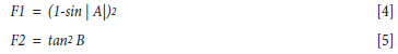
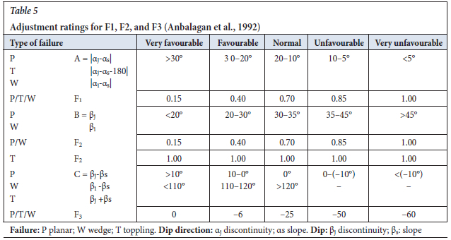
Other parameters given in Equation 3 can be explained as follows. F1 is a parameter related to the dip direction of the discontinuity (or the plunge direction of the intersection line of two planes (ai)) and slope in the rock mass, αj and αs, respectively (Anbalagan et al., 1992). F2 is explained as a parameter related to the dip of the discontinuity (βj) (or the angle of plunge of two discontinuities (βi) in the case of a wedge) that causes failure in the rock slope. This parameter is taken as 1.0 for toppling type failure (Romana, 1985). Both F1 and F2 can be calculated from the table as well as approximately calculated in Equation 4 and 5 developed by Romana (1993) as an alternative.
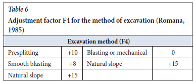
Another parameter, F3 is a parameter dependent on the dips relationships between the joints and the slope surface, in fact, which the adjustment factor range between 0 and -60 developed by Bieniawski (Romana, 1993), as illustrated in Table 5. F4, which is the final correction factor, is an adjustment factor depending on the method of excavation or blasting in the rock slope (Romana, 1985), as depicted in Table 6. In addition to planar and toppling failure modes, wedge type failure was also described by Anbalagan et al. (1992), added and taken into account for use in the SMR system. In this article, three types of failure types namely planar, wedge, and toppling were used, as developed by Anbalagan et al. (1992).
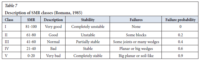
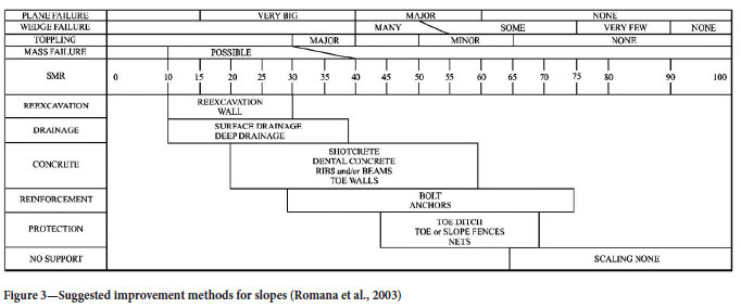
Romana (1985) defined different classes for rock slopes from very bad to very good according to the SMR score. After SMR scoring, definitions such as slope stability condition, failure type, and failure probability can be made. It was developed to guide the front end of planning for rock slope (Table 7). Also depicted is the improvement guide by Romana (2003) according to the class described (Figure 3).
Q-slope
Q-slope is a geotechnical classification system developed by Barton and Bar (2015) for engineering studies such as slope and road cuts that use six different parameters, such as RQD, Jn, Jr, Ja, Jw, and SRF as in the Q-system. However, unlike the Q-system, several parameters have been updated, and they proposed the following Equation 6 to estimate the Q-slope value (Barton, Bar, 2017).

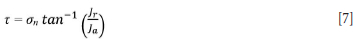
The first four parameters in Equation 6 are as in Q-system (Barton et. al., 1974) and remained unchanged. These are: rock quality definition, RQD (Deere, 1963), joint set number (Jn), joint roughness number (Jr), and joint alteration number (Ja) (Barton, Bar, 2017). RQD / Jn represents the block size. Jr / Ja is known as a friction resistance pair and can be applied to joints on either side of the wedge as needed (Barton, 2018). However, the adjustment factor for discontinuities in the rock slopes, which is called the O-factor, has been developed by Barton and Bar (2015) and it is not available in the Q-system. Another parameter is the environmental and geological condition number, which is used in this system as Jwice. This is difierent from Q-system in that the slopes are exposed to external factors (such as climate, wind, and freezing) for a very long time and Q-slope has also gained a new structure (Barton, Bar, 2015). Due to the prolonged exposure of slopes to external factors, their stability is strongly influenced by environmental and geological conditions such as climate, wind, and freeze-thaw cycles. Accordingly, slope stability is evaluated differently from the conventional Q-system, leading to the development of the Q-slope classification with a revised structure (Barton, Bar, 2015). In case of slope reinforcement or drainage measures, adjustment factors are also included, and calculations of these adjustments are given also by Barton and Bar (2015). SRF slope is the stress reduction factor for the slope. SRFa has been developed to determine the physical conditions of the slope surface and can be scored from the suggested table by Barton (2015). SRFb is similarly used in the Q-index and is a parameter developed for the stress-strength on the slope. SRFb is a very considerable parameter for highly weathering, weak, and low strength materials in rock slope. However, it becomes more important as the slope and height of the slope increase (Barton, Bar, 2017). SRFc was developed for planes of weakness that adversely affect rock slopes in many aspects. SRFslope uses the maximum value between SRFa, SRFb and SRFc. The tables suggested by Barton and Bar (2015) enable the estimation of SRFa, SRFb, and SRFc values, respectively. In other words, Jwice / SRFslope is external factors and stress. The shear resistance, τ, can be approximated using Equation 7.
However, thanks to an equation developed by Barton and Bar (2015), the steepest slope angle that can remain stable without reinforcement or improvement can be readily calculated using Equation 8 and interpreted from Figure 4.
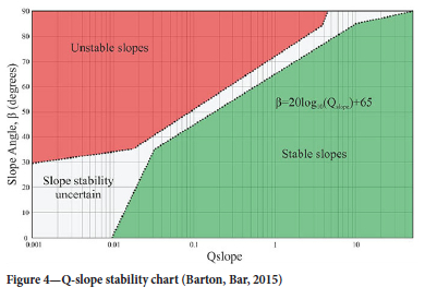

Equation 8 matches the central data for dip angles between 35 and 85. For different Q-slope grades, the angles shown in the following can be considered as fixed (Barton, Bar, 2015).
Q-slope = 10 - slope angle 85°.
Q-slope = 1 - slope angle 65°.
Q-slope = 0.1 - slope angle 45°.
Q-slope = 0.01 - slope angle 25°.
Case study
In this study, an open pit mine opened in gneiss was chosen as the study site. Albite production has been carried out in this open pit mine since 2004. It was determined by the total station measurements in the area where the eastern slopes move during heavy rainy periods in 2019. From the moment observed, production was completely stopped to prevent any loss of property or life. In addition to the use of SMR and Q-slope systems to evaluate slope stability in this mine, the studies identified unstable slopes in the mine operation and recommended necessary improvement (such as re-excavation or surface drainage) and/or reinforcement works.
Application of slope mass rating (SMR)
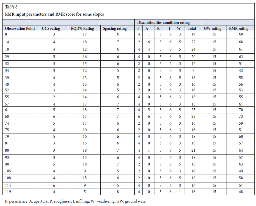
In order to use slope mass rating (SMR) classification, it is necessary to know the failure mechanism in the rock slope. The discontinuities taken from the 119 slopes in the eastern part of the open pit were transferred to the Dips V.7.016 software (2019) and the potential failure mechanism at each observation point was determined (Table I). Types of failures were detected in 76 of 119 rock slopes at the observation points. It was not included in the SMR system due to the loss of rock feature because of weathering in 43 observation points. After determining the failure mechanisms, rock mass rating (RMR) rock mass classification was conducted using all discontinuities data. The first five parameters used as input parameters in RMR classification were obtained from scanline measurements, which is suggested by International Society for Rock Mechanics (ISMR) (2007). The RMR inputs and their scores of slopes are presented in Table 8 to serve as an example, but the RMR scoring was also applied at 76 observation points.
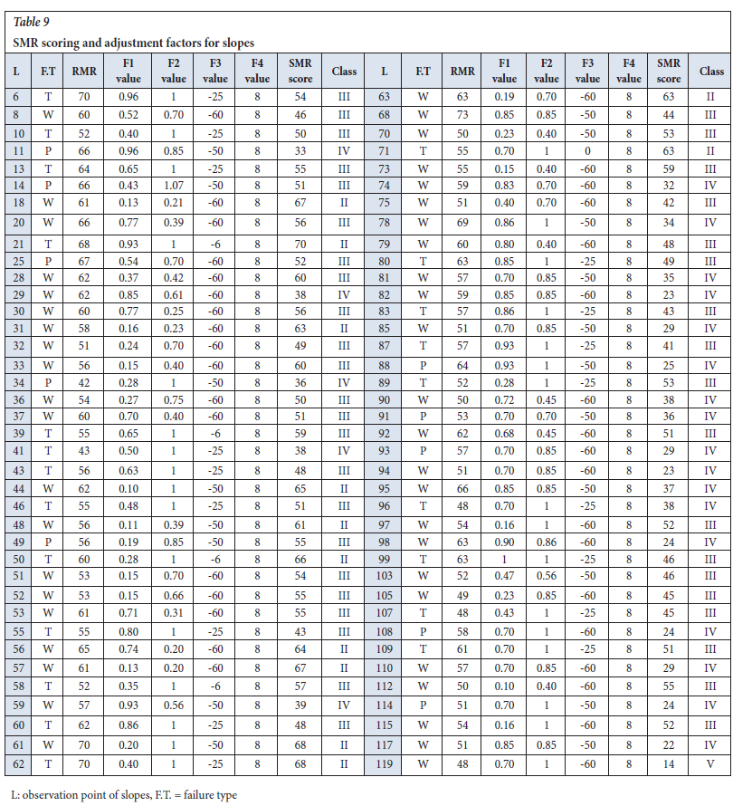
After the types of failures and RMR scores of 76 observation points were calculated, the input parameters required for SMR calculation were also collected from the field. In this process, joint and / or joint set and slope dip angle / dip direction measurements were obtained for each slope. In other words, each slope has been evaluated separately. SMR scoring, failure mechanisms, and class of the mentioned slopes are presented in Table 9.
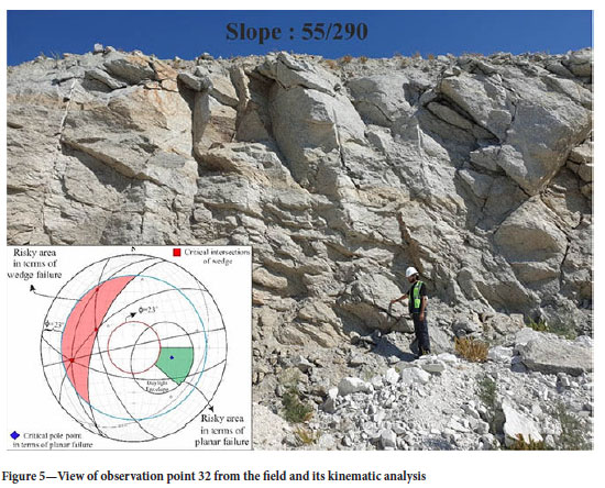
In the study area, 4 different SMR classes were identified, including 1 very bad, 22 bad, 41 normal, and 12 good. The SMR value that falls within the very good range was not detected on any observation point. The very bad rock slope is the slope number 119 (Table 9). Although these studies were carried out in the summer, the algae and rust traces observed on the discontinuity planes at the 119th observation point is an indication that there has been water outflow on the slope during rainy periods. This caused the 119th observation location to be classified as "very bad" due to the separating effect of water. However, the reason why none of the slopes are included in the "very good" class can be interpreted as the fact that the region is under tectonic regime and again, the groundwater in the region is at very high levels and the weathering effect is highly effective. Kinematically major type of failure mechanism in rock slopes is wedge-type of failure with 58% (total number of 44 location) in previous sections. Based on Romana's (1985) classification system, the third class comprises 54% of the slopes studied, representing a total of 41 locations. This ratio also belongs to the class most observed at observation points. In this classification system the possible failure modes specified in Figure 5, namely "planar or big wedge" are kinematically compatible with the major failure mechanism in the open pit mine. This harmony can be easily observed on the slope number 32 (Figure 5). SMR class in the 32nd slope is III and its kinematic failure mechanism is wedge. As seen in the Figure 5, the failure mechanism determined by Romana (1985) and the failure mechanism determined kinematically of a rock slope of SMR class III are similar. However, it can be observed in the stereographic projection that there may be a few planar failures at the same locations.
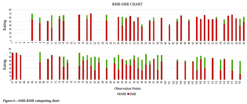
RMR scores in the rock slopes studied are between 42 and 73. SMR scores are between 14 and 70. In other words, it is seen that when the SMR decreases the RMR score decreases. As an exception, SMR score is higher than RMR score in 18 slopes (Figure 6).
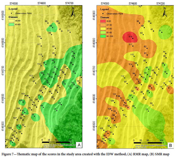
As can be seen from the graph in Figure 6, the slopes numbered 18, 21, 31, 33, 39, 44, 48, 50, 51, 52, 57, 58, 63, 70, 71, 73, 89, and 112 are more than SMR points. This is because it can be said that the relationship between discontinuity and slope angles in the SMR system is more favourable than other rock slopes. This caused the SMR to be higher than RMR. In order to better interpret the SMR and RMR scoring made in the open pit and to evaluate the scores in the individual slope scale, the scoring has been depicted by using the IDW method via QGIS (3.30) software (Figure 7).
As can be seen in the figures, it is clearly observed that the adjustment factors in SMR scoring decrease the RMR score. According to the RMR scores given in Table 9, in any of the 76 rock slopes, it was not classified as "very bad rock" and "bad rock". In the classifications made on 76 rock slopes in the SMR class, one of them was classified as very bad and 22 of them were bad. To be expressed as a percentage, the sum of slopes included in the very bad and bad rock class was determined as 30% in the SMR classification system, while this rate is 0% in the RMR system. Again, in the SMR system, the rock slope in the normal class (III) is 54%, while this rate is 64% in the RMR class. The most significant percentage difference belonging to the same rock slopes was determined in the rock class belonging to the "good" class. While the rate of slopes in the "good rock (II)" class in the SMR system is 16%, this rate is calculated as more than twice in the RMR system, that being 36%.
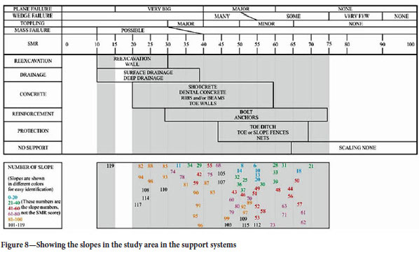
In addition to the SMR classification system, Romana (2003) has also proposed some improvement and support systems. Each of the 76 rock slopes studied on this figure developed by Romana (2003) is shown separately (Figure 8). As a result of the study on 76 slopes, different improvement and support methods were determined. There are no slopes belonging to the place shown with white background. In addition, details regarding the scores of the slopes are indicated in the legend. As can be seen from Figure 8, in the improvement diagramme made according to the SMR score, all slopes can suggest one or more improvement or strengthening. As previously stated, rock slopes classified as third class are densely distributed, as illustrated in (Figure 8).
For example, slope number 46 has a score of 51.1. According to the improvements suggested by Romana (1985), many different improvements can be made on this slope such as shotcrete, bolt anchors, and toe ditch. Another example can be given to slopes 119, 82, 98, and 110. Improvement works for these slopes should be different than others. Improvement works such as re-excavation or surface drainage should be done on these slopes. The different comments that can be made for other slopes can be easily examined in the diagramme developed by Romana (2003). It should not be forgotten that these reinforcement or support systems are only a guide. Different systems can be developed according to the production activity or the expenses of the contractor company.
Application of Q-slope
Q-slope is another classification system used in this article to better examine and evaluate the slope stability. As mentioned in the slope stability assessment section, it is an empirical system developed by Barton and Bar (2015) in order to evaluate the rock slopes with different parameters and to determine the steepest slope angle that can remain stable without any reinforcement at the first stage of the project (Barton, Bar, 2017). Within the scope of this study, the slopes at 76 observation points in the open pit mine were scored based on the tables and equations suggested by Barton and Bar (2017). In the mining operation, all slopes were realised in orthogneiss mass, and all of the slopes have a height of less than 30 metres (average heights of the slopes of 10-12 metres). This example, inspired by Barton and Bar (2015), copies the existing information about this system. This illustrates the proper implementation of the technique at an albite mine located in Turkey. RQD value, which is one of the first 6 parameters of the formula developed specifically for this system, is a parameter used in the RMR system, which is necessary for calculating SMR; the values were utilised based on the calculations performed using the RMR system outlined in the preceding section. Another parameter of the formula, Jn (number of discontinuous sets) was determined as a result of scanline measurements. It should be noted here that the measurements taken for each slope are unique and have been considered independently of other slopes. Jr/Ja is evaluated differently for each slope outcrop. Here, it was scored for the most unfavourable joint set as suggested for the O-factor developed by Barton and Bar (2015). In wedge-type failures, the secondary joint set that causes failure was given appropriate scores, also developed by Barton and Bar (2015). In order to calculate Jwice, which is another parameter developed differently from the Q-system, the amount of precipitation and temperature that the region experiences according to months by using the local meteorological resources of the country.
Based on these data, the 'wet environment' class was selected, which is one of the categories recommended by Barton and Bar (2015). The reason for this is that as can be seen from the data, the region receives heavy rainfall, especially in winter, and the average temperature is low during these rainy periods. During the investigations carried out in the summer periods, it was determined that the slope steps were stable (production stopped), but because of the characteristics of the discontinuity of planes on the slopes (orientation, roughness, spacing, etc.) it was found to be "incompetent" rock. In other words, for this study, the Jwice value of each slope was determined as 0.6. In addition, when there was no drainage and / or reinforcement system in the proposed graph in any bench of the pit slopes, it was not multiplied by any coefficient.
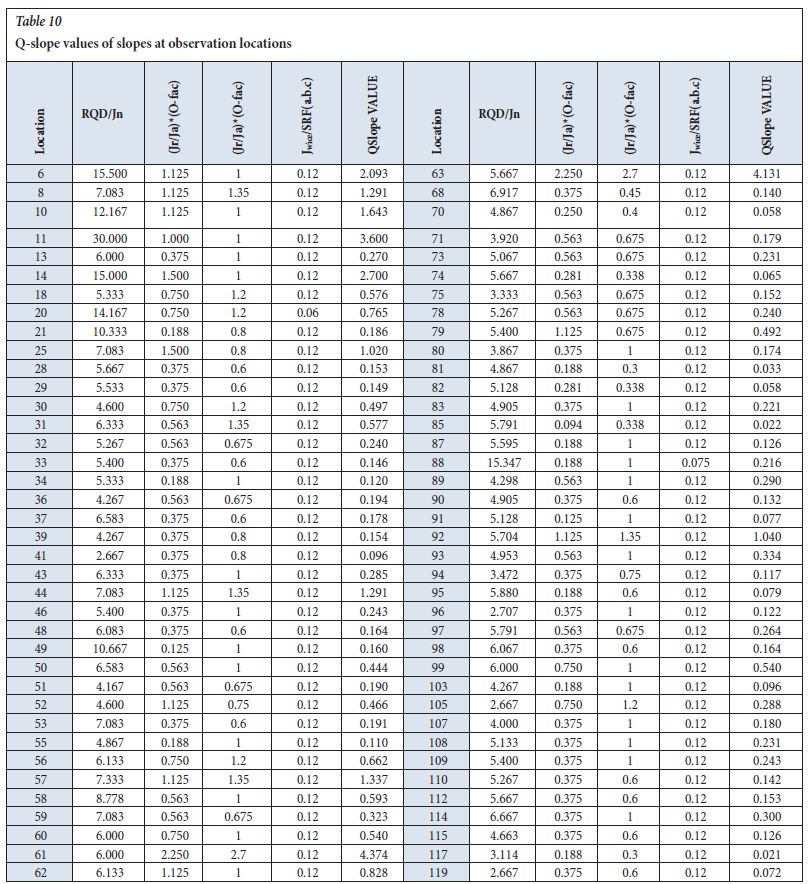
Observation points for the SRFa parameter were evaluated separately. As a result of these observations, it was thought that there were large block falls on the slopes due to blasting and there was a rock slope sensitive to weathering. Considering these situations, the B description class suggested in the scoring system for the rock slope is given, namely "Loose blocks, signs of tension cracks and joint shearing, susceptibility to weathering, severe disturbance from blasting". One of the parameters required to define the SRFb parameter is UCS, and this parameter was determined empirically by using an L-type Schmidt hammer in the field. The second parameter is the maximum principal stress. This parameter is calculated by RocLab V.0.1 software by following the generalised Hoek and Brown failure criterion (Hoek, Brown, 1997) for jointed rock mass (RocScience, 2007). As a result of these operations, σc / σ1 value was calculated and SRFb score was found. The SRFc value, which is the last denominator of the system, was again realised by defining the main discontinuity sets from the observation points. A different SRFc score was found for each slope. According to Barton and Bar (2015), the highest value of SRFa, b, and c, values were included in the calculation. At the end of all these processes, after the necessary calculations were made at 76 observation points, the Q-slope score of each slope was revealed (Tabel 10).
After the Q-slope scores were calculated, they were placed in the semi-logarithmic table proposed by Barton and Bar (2015) ( Figure 9). All rock slopes are indicated by black points.
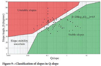
According to this classification system, 31 stable, 27 unstable, and 18 uncertain classes were determined as a result of the analyses performed on a total of 76 slopes. The proportional values of these classes were determined as 41%, 35%, and 24%, respectively.
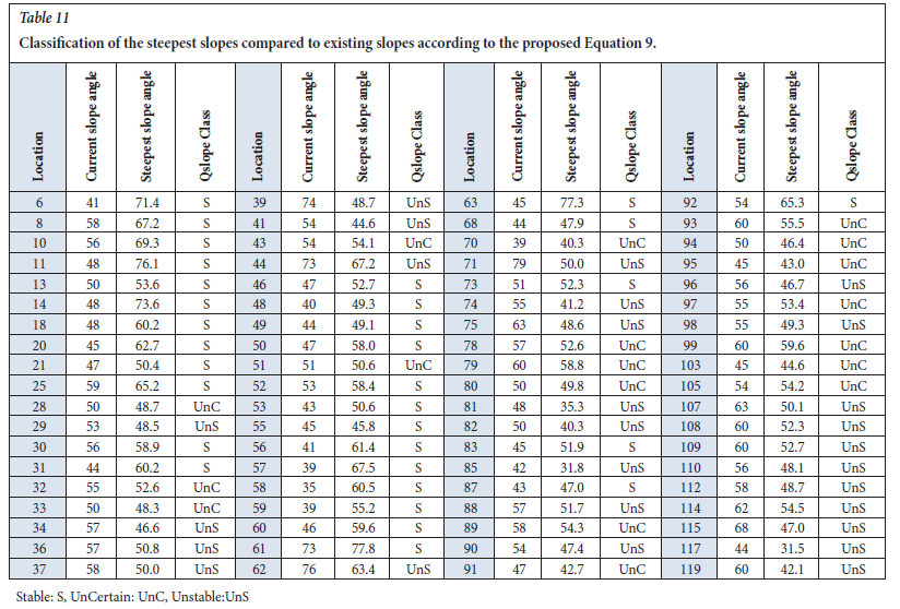
Barton and Bar (2015) stated that, in addition to the diagramme in Figure 9, the steepest slope angle that can remain stable without reinforcement and a support system can be found with a simple Equation 9.

It is possible to classify the rock slope by comparing the current slope angles of the aforementioned slopes and the steepest slope angles produced by the formula developed by Barton and Bar (2015). In the analysis made within the scope of this study, the steepest slope angle was determined by both methods (Table 11).
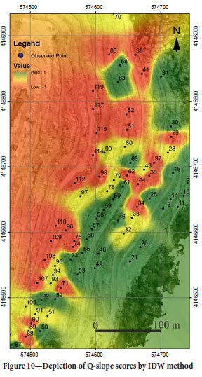
According to the results of Q-slope on 76 slopes, 18 uncertain classes were determined. These slopes can become stable in the classification system empirically made even by only reducing the slope angles by a few degrees. To give an example, the slope number 51 is included in the stable class only by reducing the angle with a difference of 0.43 degrees. In other words, the slope can become stable in relation to the material properties with the necessary slope angle reduction process that can be made on slopes. However, the openings of several slopes that appear to be 'stable' in the table were reduced more than necessary. This increases the cost of excavation and causes loss of time. Some of the mentioned slopes can be given as 18, 31, 48, 56, 57, and 63. Classes were depicted by the IDW method using a QGIS program to show the spread of Q-slope classification in the field and slope scale. During this mapping process, the classification developed by Barton and Bar (2015) was used. Since the program uses the IDW method only as a numerical value, stable slopes are given 1, uncertain slopes 0, and unstable slopes -1 values. Following the coding process, its spatial distribution was illustrated on the mining area located on a slope of 76°, using the IDW interpolation method (Figure 10).
Results
The research area is located within the Menderes Massif, an important tectonic zone of the Anatolides prominent in Western Anatolia (Graciansky, 1965). This study used the scan-line technique advocated by ISRM (2007) and covered 119 observation points in the eastern part of the albite open pit mine that opened in gneiss (Figure 1). A total of 1613 discontinuity measurements were carried out at these points and the data, including discontinuity orientation, spacing, persistence and roughness, were evaluated according to ISRM (2007) guidelines. As a result, the dominant failure type detected was wedge (58%).
In light of the kinematic failure potential observed in this mining region, two rock mass classification systems have been used: SMR and Q-slope. For SMR classification, kinematic failure type has to be evident. Four SMR classes were identified in the study area: 1 very poor, 22 poor, 41 fair, and 12 good. No slopes fell into the 'very good' range due to the tectonic activity of the region and high groundwater levels that tend to exacerbate the effects of weathering. The majority of the observed failures (58%) were wedge failures.
In the 76 slopes examined, various improvement and support methods were suggested by Romana (1985). These methods range from shotcrete and bolt anchors to re-excavation and surface drainage, depending on slope characteristics. Additionally, slopes at 76 observation points were scored using Barton and Bar (2017) tables and equations and the relevant Q-slope scores were revealed (Table 10). According to this classification system, 31 slopes were evaluated as stable, 27 slopes as unstable, and 18 slopes as uncertain. The rates of these classes are 41%, 35%, and 24%, respectively. In particular, slope 18, which was initially classified as uncertain, was able to achieve stability with slight angle adjustments, as was the case for slope 51, which was classified as stable with an angle reduction of only 0.43 degrees.
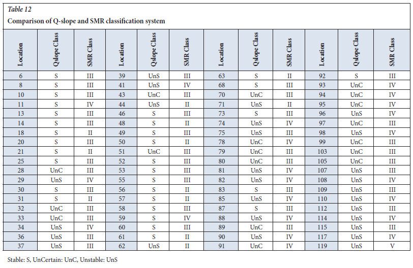
According to field observations and classification systems, many slopes in both systems can be defined as 'unstable'. Examples of this are presented in Table 12. As a result of the analysis, it is clearly observed that the slopes numbered 29, 34, 41, 74, 81, 82, 82, 85, 88, 90, 96, 98, 98, 108, 110, 114, 117, and 119 are observed as "unstable" in both classification systems. The reason for this is that these slopes are extremely altered (HW) and the fracture-cracks are extremely intense. It was observed that UCS and %RQD values were low on the slope surfaces and therefore the slopes were extremely unstable in both classification systems. On the other hand, some slopes were classified as 'stable' in the Q-slope system, while some slopes were classified as 'unstable' in the SMR. These slopes are observation points 11 and 59. The reason for this is that the 'current slope angle' value in the Q-slope classification system is considerably smaller than the 'maximum slope angle' value. Since this value is not observed in the SMR system, differences are observed in both classification systems. Besides, the opposite situation was also observed. In other words, some slopes classified as 'unstable' in the Q-slope were classified as 'stable' in the SMR. The slopes in question are slopes 44, 62, and 71. The reason for this is that the UCS and %RQD values are very high. Therefore, RMR and consequently, SMR values are high. However, since the slope angle is extremely steep, the class of the slopes is considered to be "unstable" in the Q-slope (Table 12).
As a result of this study on gneiss rock slope, it is thought that the use of both classification systems in terms of providing very practical and fast information in pre-stabilisation studies will guide future studies. It is expected to give more accurate results qualitatively due to the kinematic analysis for the use of the SMR system, followed by the use of the RMR classification system. In the next stage of the study, the 'slopes with sliding potential' observed in the region can be studied in more detail and the 'factor of safety (FoS)' can be calculated on these slopes by numerical analysis method, and by comparing the values calculated both numerically and kinematically, the studies can be continued with the safest and maximum efficiency.
Acknowledgment
The authors' thank the two anonymous reviewers for their very constructive and valuable comments, which significantly led to the improvement of the paper. We would also like to express our gratitude to M.Sc Geological Engineering, Melikhan Karakas and PhD. Geological Engineering, Saffet Deniz Karagoz, who directly contributed to the studies carried out in the field.
Statements and declarations
Funding
The authors declare that no funds, grants, or other support were received during the preparation of this manuscript.
Conflict of interest
The authors have no relevant financial or non-financial interests to disclose. On behalf of all authors, the corresponding author states that there is no conflict of interest.
Author contributions
All authors contributed to the study conception and design. Material preparation, data collection and analyses were performed by Enes KALHAN, Cem KINCAL. The first draft of the manuscript was written by Enes KALHAN and all authors commented on previous versions of the manuscript. All authors read and approved the final manuscript. Also, the work in this manuscript was conducted from the first author's Master Thesis.
Consent for publication
All authors mutually agreed to publish the work in this journal.
References
Anbalagan, R., Sharma, S., Raghuvanshi, T. K. 1992. Rock mass stability evaluation using modified SMR approach. In Proceedings of the 6th National Symposium on Rock Mechanics. pp. 258. [ Links ]
Anon. 1977. The description of rock masses for engineering purposes. Quarterly Journal of Engineering Geology, vol. 10, pp. 43-52. [ Links ]
Azarafza, M. 2020. Application of the modified Q-slope classification system for sedimentary rock slope stability assessment in Iran. Engineering Geology, vol. 264, no. 105349. https://doi.org/10.1016/i.ENGGEO.2019.105349 [ Links ]
Bar, N., Barton, N. 2017. The Q-slope method for rock slope engineering. Rock Mechanics and Rock Engineering, vol. 50, no. 12, pp. 3307-3322. https://doi.org/10.1007/S00603-017-1305-0 [ Links ]
Barton, N., Bar, N. 2015. Introducing the Q-slope method and its intended use within civil and mining engineering projects. ISRM Regional Symposium Eurock 2015 and 64th Geomechanics ColloquiumAt: Salzburg. [ Links ]
Barton, N., Choubey, V. 1977. The shear strength of rock joints in theory and practice. Rock Mechanics, vol. 10, no. 1-2, pp.1-54. https://doi.org/10.1007/BF01261801 [ Links ]
Barton, N., Lien, R., Lunde, J. 1974. Engineering classification of rock masses for the design of tunnel support. Rock Mechanics, vol. 6, no. 4, pp. 189-236. https://doi.org/10.1007/BF01239496 [ Links ]
Basahel, H., Mitri, H. 2017. Application of rock mass classification systems to rock slope stability assessment: A case study. Journal of Rock Mechanics and Geotechnical Engineering, vol. 9, no. 6, pp. 993-1009. https://doi.org/10.1016/J.JRMGE.2017.07.007 [ Links ]
Bell, F.G. 2004. Engineering geology and construction. CRC Press. https://doi.org/10.1201/9781482264661 [ Links ]
Bieniawski, Z.T. 1989. Engineering rock mass classifications: a complete manual for engineers and geologists in mining, civil, and petroleum engineering. John Wiley & Sons. [ Links ]
Branch, Z., Ravoshti, D.A., Hajiagha, L.F. 2018. Utilization of the Q-slope empirical classification system in jointed rock slopes: A case study for Bonab-Malekan highway. Journal of Geotechnical Geology, vol. 14, no. 2, pp. 193-196. [ Links ]
Candan, O., Çetinkaplan, M., Oberhänsli, R., Rimmelé, G., Akal, C. 2005. Alpine high-P/low-T metamorphism of the Afyon Zone and implications for the metamorphic evolution of Western Anatolia, Turkey. Lithos, vol. 84, no. 1-2, pp. 102-124. https://doi.org/10.1016/J.LITHOS.2005.02.005 [ Links ]
Cernica, J.N. 1995. Geotechnical engineering: Soil mechanics. Chichester. John Wiley and Sons Inc. [ Links ]
Coduto, D.P. 1999. Geotechnical engineering: Principles and practices. Prentice-Hall Inc. [ Links ]
Das, B.M., Sobhan, K. 1994. Principles of geotechnical engineering (8th ed.). PWS Publishing Company. [ Links ]
Deere, D.U. 1964. Technical description of rock cores for engineering purposes. Rock Mechanics and Engineering Geology, no. 1, pp. 17-22. [ Links ]
Deere, D.U. 1989. Rock quality designation (RQD) after 20 years. U.S. Army Corps of Engineers Contract Report, vol. 89, no. 1. [ Links ]
Graciansky, P. 1965. Precisions sur le métamorphisme du massif de Menderes le long de sa bordure méridionale. Bulletin of the Mineral Research and Exploration Institute of Turkey, vol. 64, pp. 9-23. [ Links ]
Hoek, E. 2006. Rock mass properties, In Practical rock engineering, pp. 1-47. University of Toronto Press. [ Links ]
Hoek, E., Bray, J.W. 2004. Rock slope engineering. London: Institution of Mining and Metallurgy. [ Links ]
Hoek, E., Brown, E.T. 1997. Practical estimates of rock mass strength. International Journal of Rock Mechanics and Mining Sciences, vol. 34, no. 8, pp. 1165-1186. https://doi.org/10.1016/S1365-1609(97)80069-X [ Links ]
Ietto, F., Perri, F., Cella, F. 2018. Weathering characterization for landslides modeling in granitoid rock masses of the Capo Vaticano promontory (Calabria, Italy). Landslides, vol. 15, no. 1, pp. 43-62. https://doi.org/10.1007/S10346-017-0860-5 [ Links ]
International Society for Rock Mechanics (ISRM). 2007. The Complete ISRM Suggested Methods for Rock Characterization, Testing and Monitoring: 1974-2006. Suggested Methods Prepared by the Commission on Testing Methods; Ulusay, R., Hudson, J.A., Eds.; ISRM Kozan Ofset: Ankara, Turkey. [ Links ]
Jhanwar, J.C. 2012. A classification system for the slope stability assessment of opencast coal mines in central India. Rock Mechanics and Rock Engineering, vol. 45, no. 4, pp. 631-637. https://doi.org/10.1007/S00603-012-0223-4 [ Links ]
Jordá-Bordehore, L. 2017. Application of Q slope to assess the stability of rock slopes in Madrid Province, Spain. Rock Mechanics and Rock Engineering, vol. 50, no. 7, pp. 1947-1957. https://doi.org/10.1007/S00603-017-1211-5 [ Links ]
Kadakçi, T. K., Koca, M. Y. 2014. Açik ocak albit işletmesindeki kaya şevlerinin sonlu elemanlar yöntemi kullanilarak duraylilik değerlendirmesi. Jeoloji Mühendisliği Dergisi, vol. 38, no. 1, pp. 1-19. [ Links ]
Karagöz, S.D., Kincal, C., Koca, M.Y. 2020. Investigation of the causes of an instability in an albite mine opened in menderes massif and monitoring slope movements before the failure employing robotic total station equipment. Journal of Geological Engineering. vol. 44, pp. 41-66. DOI 10.24232/jmd.740511 [ Links ]
Kiliç, R. 2005. Kaya mekaniği ders notlari, vol. 39, pp. 61-90. AÜFF Döner Sermaye İşletme Yayinlari. [ Links ]
Kincal, C. 2014. Application of two new stereographic projection techniques to slope stability problems. International Journal of Rock Mechanics and Mining Sciences, vol. 66, pp. 136-150. https://doi.org/10.1016/J.IJRMMS.2014.01.006 [ Links ]
Morales, M., Panthi, K. K., Botsialas, K. 2019. Slope stability assessment of an open pit mine using three-dimensional rock mass modeling. Bulletin of Engineering Geology and the Environment, vol. 78, no. 2, pp. 1249-1264. https://doi.org/10.1007/S10064-017-1175-4 [ Links ]
Myat, A., Aung, D., New, H. 2022. Ground improvements for landslide prevention along the road between Kywedatson and Wetphyuye, Mandalay Region and Shan State, Myanmar (Doctoral dissertation). University of Yangon Research Journal, vol. 11. [ Links ]
Pantelidis, L. 2009. Rock slope stability assessment through rock mass classification systems. International Journal of Rock Mechanics and Mining Sciences, vol. 46, no. 2, pp. 315-325. https://doi.org/10.1016/J.IJRMMS.2008.06.003 [ Links ]
Priest, S.D., Hudson, J.A. 1976. Discontinuity spacings in rock. International Journal of Rock Mechanics and Mining Sciences and Geomechanics Abstracts, vol. 13, no. 5, pp. 135-148. https://doi.org/10.1016/0148-9062(76)90818-4 [ Links ]
Riquelme, A.J., Tomás, R., Abellán, A. 2016. Characterization of rock slopes through slope mass rating using 3D point clouds. International Journal of Rock Mechanics and Mining Sciences, vol. 84, pp. 165-176. https://doi.org/10.1016/J.IJRMMS.2015.12.008 [ Links ]
Rocscience Inc. 2007. RocLab V0.1: Rock mass strength analysis using the generalized Hoek-Brown failure criterion. [ Links ]
Rocscience Inc. 2019. Dips - 7.016: Graphical and statistical analysis of orientation data. [ Links ]
Romana, M. 1985. New adjustment ratings for application of Bieniawski classification to slopes. In Proceedings of international symposium on the role of rock mechanics, pp. 49-53. ISRM. [ Links ]
Romana, M.R. 1993. A geomechanical classification for slopes: Slope mass rating. In Comprehensive rock engineering, vol. 3, pp. 575-600). https://doi.org/10.1016/B978-0-08-042066-0.50029-X [ Links ]
Romana, M., Tomás, R., Serón, J.B. 2015. Slope mass rating (SMR) geomechanics classification: Thirty years review. Rock Mechanics and Rock Engineering, vol. 50, no. 7, pp. 1947-1957. https://doi.org/10.1007/S00603-017-1211-5 [ Links ]
Sandria, L.A., Indrawan, I.G., Hendrayana, H. 2023. Rock mass characterizations and kinematic analysis for construction design method of diversion tunnel of Dolok Dam, Central Java. E3S Web of Conferences, vol. 468, no. 02005. https://doi.org/10.1051/E3SCONF/202346802005 [ Links ]
Siddique, T., Alam, M.M., Mondal, M.E.A., Vishal, V 2015. Slope mass rating and kinematic analysis of slopes along the national highway-58 near Jonk, Rishikesh, India. Journal of Rock Mechanics and Geotechnical Engineering, vol. 7, no. 5, pp. 600-606. https://doi.org/10.1016/J.JRMGE.2015.06.007 [ Links ]
Singh, B., Goel, R.K. 2011. Engineering rock mass classification, pp. 1755-1315. Boston: Butterworth-Heinemann. pp. 1-365. https://doi.org/10.1016/C2010-0-64994-7 [ Links ]
Terzaghi, K. 1946. Rock defects and loads on tunnel supports. Commercial Shearing and Stamping Company. [ Links ]
Ulusay, R., Hudson, J.A. 2007. The complete ISRM suggested methods for rock characterization, testing and monitoring. International Society for Rock Mechanics-Turkish National Group. [ Links ]
 Correspondence:
E. Kalhan
Email: e.kalhan@ogr.deu.edu.tr
Received: 20 Nov. 2024
Revised: 11 Jun. 2025
Accepted: 15 Jun. 2025
Published: August 2025
