


Services on Demand
Journal

Article
 English (pdf)
 Article in xml format
 Article references
 Send this article by e-mail
Indicators
Related links
-
 Cited by Google
 -
 Similars in Google
Share

 Permalink
R&D Journal
On-line version ISSN 2309-8988Print version ISSN 0257-9669
R&D j. (Matieland, Online) vol.22 Stellenbosch, Cape Town 2006
Stand Alone Accelerometer Sensor System for an Egg-Drop Contest
Alex A. ElvinI; Niell G. ElvinII
ISenior Lecturer, School of Civil and Environmental Engineering, University of the Witwatersrand, Johannesburg, South Africa. Correspondence to: Alex Elvin, School of Civil and Environmental Engineering, Private Bag 3, Wits, 2050, South Africa. Email: elvin@civil.wits.ac.za
IIAssistant Professor, Department of Civil and Environmental Engineering, Michigan State University, East Lansing, Ml, USA
ABSTRACT
An egg drop contest was recently held at the University of the Witwatersrand. In this contest, structures were built to protect a raw chicken egg when dropped 15 meters onto a hard surface. No aerodynamic retarding devices were allowed. Of the thirteen entries only two survived the fall. The obvious question for this deceptively simple problem is "What kind of accelerations and forces occur during impact?" To answer these questions this paper describes the research and development that went into designing an accelerometer sensor system. The system that was developed used a ±70g accelerometer, capable of data sampling at 1000 points per second with a 10bit resolution. The acceleration data was stored to on-board non-volatile memory. Subsequently to recording, the data could be downloaded to a PC via a serial link. In the developed system, thirty two seconds of data could be recorded. This allowed for multiple drop tests to be conducted in one recording period. The developed system architecture readily supports future expansion to a multiple axis accelerometer, as well as longer recording periods. The experimental data match the results from a theoretical model of the egg drop test for various drop heights.
Keywords: Stand alone accelerometer, Data Acquisition, Data Logging, Egg drop contest, Impact modelling.
NOMENCLATURE
English Nomenclature
AIntegration Constant
aacceleration
BIntegration Constant
C Damping constant
EEPROM Electrically Erasable Programmable Read-Only Memory
FRAM Non-volatile random access memory; Product of Ramtron Corp.
f Natural frequency, in Hertz
gGravitational constant 9.81 m/s2
mgMilli-g 9.81x10⁻³ m/s2
hDrop height
kSpring stiffness
mmass
PC Personal Computer
tTime
uDisplacement
ὑDisplacement derivative with respect to time, ie, Velocity
ü Velocity derivative with respect to time, ie, Acceleration
VInitial velocity
V Volts
Greek Nomenclature
ζDamping ratio
ωNatural frequency in radians/second
Introduction
Recently an egg drop contests was held at the University of the Witwatersrand. In this contest a structure housing an egg was dropped fifteen meters onto a hard surface. The aim of the contest was for the designed structures to protect their egg payload. The egg drop is a structural engineering problem where the structure is subject to impact loading. Although deceptively simple, only two out of thirteen entrants succeeded in protecting their eggs1. The question became: how difficult is the egg drop problem? and what are the forces that develop during the egg's fall?
This paper describes the stand-alone sensor system that was developed to measure the accelerations that an egg would experience during impact. The magnitude of the impact acceleration is directly related to the force on the egg and thus determines whether the egg will survive the drop. The summary of the results obtained with the developed system is presented in this paper; a full description of the experiments together with theoretical modelling is presented in [1].
Egg drop contests at high school and university levels have been held all around the world for a long time. (For a few references see [2], [3], and [4]). In general most competitions allow parachutes and other aerodynamic devices that slow the descent of the egg. One of the rules in the present contest was that no specific aerodynamic retardation was allowed. This required the careful consideration of structural and material concepts, instead of aerodynamic design. With a 15 meter drop, and no air deceleration allowed, the present egg drop contest is a deceptively simple engineering problem.
The paper is structured as follows. First the egg drop contest, its rules and a few of the solutions are presented. Next the accelerometer sensor system architecture is laid out and the data management system is discussed. Then the methods of sensor calibration and the required data acquisition rates are described.
A few typical results measured by the system are presented. Considering the effect of drop height on the egg's acceleration concludes the paper.
Please note that the engineering details pertaining to the egg drop structure are specifically omitted, since we plan to conduct similar contests in the future.
The Contest
The egg drop contest was a voluntary project that was open to anyone who wished to enter. The entrants could design and build their structures based on analysis, experiments and/ or intuition. The problem was open ended, i.e. no solution concept, material or method of building was suggested or favoured. The entries had to conform only to the contest's rules.
Rules
The structure housing the egg was to be dropped 15 meters off the University of the Witwatersrand Civil and Environmental Engineering Building and land on the tarmac below.
The main rule was that aerodynamic retardation of the free fall of the structure was not allowed. Thus parachutes, air brakes, and gliding/ winged mechanisms and animals were prohibited. The other rules were:
1. The structure had to be easily deployable. Eggs were handed to the contestants two hours before they were to be dropped.
2. After the drop, the eggs had to be easily removable from the structure.
3. No tampering with the eggs was allowed, eg, hard-boiling, or chemically altering the eggs etc.
4. The structure had to land within 5x10meter area below the drop point.
5. The structures were suspended on a cantilever. A maximum 10cm string could be used as the suspension cord to centre and level the structure.
Solutions
The contest attracted thirteen entrants. Although all entries were different, especially in the detailing, in the main only two structural philosophies were pursued:
1. The egg was surrounded by a cushioning material. This material was encased in a container. (See Figure 1a)
2. The egg was suspended within a structure by rubber elastics. (See Figure 1b).
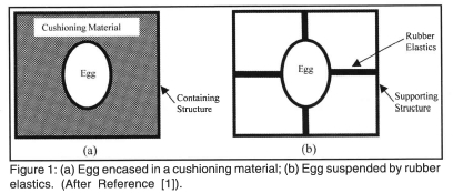
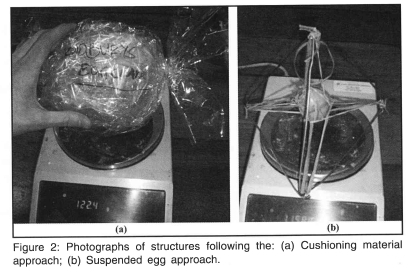
Figure 2 shows some examples from the two types of structures.
Results
Of the thirteen eggs that were entered, only two survived the 15meter fall with no damage. The question now arises: "How difficult is the egg drop problem?" To answer this question, it was decided to measure the accelerations of the egg during impact. Since the suspended egg approach was by far the most popular solution, it was used as the platform to answer the above question.
The remainder of this paper deals with the research and development process that went into developing such a sensor unit. A fuller description of the results of the egg drop contest, together with the theoretical modelling and experimental measurements is given in reference [1].
The accelerometer sensor system
Introduction
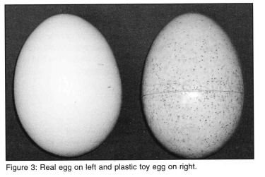
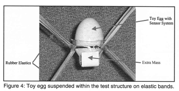
To measure the egg accelerations a test structure was built. A toy egg that could be opened, and made of thin plastic, having similar dimensions to a real egg, was used in the experiments (see Figure 3). The electronic sensor system was to be housed within this egg. The toy egg was suspended on rubber bands (as shown in Figure 4); the supporting structure (not shown) was much stiffer than the elastic bands ensuring that the egg underwent dynamic oscillations, and the structure could be used multiple times. To match the dynamic accelerations that a real egg would undergo during impact, the weight of the plastic egg was increased. Eggs are advertised to weigh no less than 50 grams. The weight of the toy egg, sensor circuit, housing and elastic bands was increased to 72 grams by taping coins to the bottom of the housing as shown in Figure 4.
Sensor Requirements
To capture adequately the acceleration data of the suspended real egg, the requirements from the sensor system are:
(a) The physical dimensions of all electronics and power source must fit into the plastic egg.
(b) The accelerometer range should be greater than the maximum impact acceleration. This maximum acceleration is not known a priori.
(c) There must be sufficient resolution (number of bits per unit of acceleration) of the data acquisition system.
(d) The sampling rate must be adequate. This rate depends on the duration of the impact event.
(e) The method of recording the impact event must be reliable.
Preliminary Considerations
Since the sensor system had to fit into the plastic egg, the power source had to be considered first. Tethered systems, where the power would be supplied via wires, were ruled out immediately since the tether would be difficult to manage and could alter the dynamic behaviour of the egg. The power source thus had to be a battery. There are many commercial batteries from which to choose. The main restrictions are:
(a) the size of the battery,
(b) the power of the battery, and
(c) the commercial availability2.
Although high in power compared to other solutions, the size restriction precludes the use of a standard 9 V battery. From a size and power point of view, a 3 V button cell battery is the optimal solution. Thus it was clear from the start that the button cell battery (or batteries) needed to be used as the power source.
The second question to be addressed was the method of recording the data once it was measured. Two options are possible:
(a) real-time data telemetry via radio, or
(b) store the data in memory for later download.
The first method requires no wires, and only a transmitter circuit on board the sensor system. The second method requires memory chips to be included on the sensor and a hardware port to allow for download. This makes the second option somewhat bigger in real estate size. However, the fidelity of the second system is much higher, since there is no chance of loosing the data through corrupt radio communication. Since the impact event could be of short duration, loosing even a small number of data points would render the whole drop experiment meaningless. In general, data stored in local memory is more robust than data transmitted via radio communication. For this reason, it was decided to store all data on board the sensor for later download.
Sensor and Data Acquisition Issues
The next issue that was considered was data acquisition. This includes:
(1) the required speed of analog to digital conversion,
(2) the resolution (number of bits) of the acceleration that was required, and
(3) the magnitude of accelerations that could be expected during the impact events.
The answers would allow to layout the architecture of the sensor system. A mathematical model also presented in more detail in [1] was used to answer these questions.
The egg was considered as a single degree of freedom system suspended on springs and dashpots (see Figure 5). Upon impact the test structure is assumed to remain stationary.
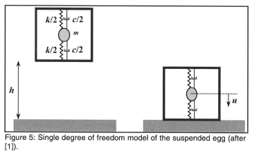
The governing equation of motion, in terms of the displacement w, of the egg is the standard:

where the symbols m is the mass of the egg, c is the damping, and k is the spring stiffness. (See Figure 5). Equation (1) is mass normalized to give:
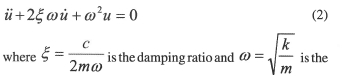
natural frequency of the system measured in radians/second.
Equation (2) is solved using standard techniques (see for example Reference [5]) and yields a solution for the displacement of the egg:
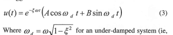
where ζ < 1). Constants A and B are obtained from the initial conditions.
The acceleration is given in [1] by:

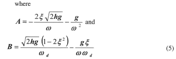
Here h is the height of the drop and g is the gravitational acceleration. As can be seen from the above equations there are only two system parameters (related to egg's mass, M, and material parameters k and c): the damping ratio ζ and the natural frequency ω.
These parameters were obtained by first clamping the base of the structure, applying an initial velocity to the egg, and then measuring the resulting acceleration trace. Equation (2) was then solved with the initial conditions:
And can be used with Equation (4), the acceleration history, to determine the system parameters.
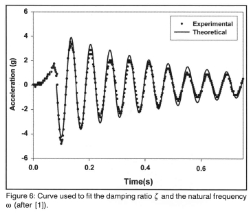
The experimental accelerations were fitted using the theoretical curve given by Equation (4) together with parameters given by Equation (6) and least squares to obtain the optimum values for ζ and ω. The measured accelerations (dots) and the theoretical curve with the best-fit parameters (solid line) are shown in Figure 6. For the test structure the least squares damping ratio was calculated as ζ = 2.5% and the natural frequency ω.d = 90.48 rad/sec (corresponds to a natural frequency of f = 14.4Hz).
After impact the egg is expected to oscillate freely at 14.4Hz or complete one cycle in 69.4 milliseconds. The full cycle is assumed to be described by 30 points. This gives a minimum data acquisition speed of 432 samples per seconds. To be conservative, the data acquisition speed was set to 1000 samples/second in the sensor system. This gives a resolution of 1 millisecond.
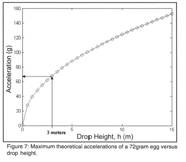
To determine the magnitude of accelerations during impact, the maximum accelerations on impact from Equation (4) and (5) are plotted against the drop height in Figure 7. As can be seen from this figure the theoretical accelerations can be as high as 149g when the drop is 15 meters (the drop height in the contest). Accelerometers to measure such relatively high acceleration ranges are available commercially. However, it was decided to perform the experiments under controlled laboratory conditions. This would verify and calibrate the theoretical model. In this case the maximum drop height would be 3 meters (height of the laboratory ceiling). The corresponding maximum theoretical acceleration at 3 meters is almost 67 g. The ADXL78 accelerometer (model number AD22281), from Analog Devices Inc, has a range of ± 10g and thus should be adequate to measure the accelerations for the laboratory drop tests.
The specification sheet for the ADXL78, [8], states that this accelerometer contains internal circuitry that provides a 2-pole Bessel filter with a -3dB frequency at 400Hz. It is expected that during the drop, the egg will undergo accelerations that have frequency components significantly less than the 400Hz band-width of the ADXL78. The noise density for the sensor is quoted as  [8]. This noise density is insignificant when compared to the peak accelerations (up to a maximum of ± 70g)expected during the egg drop.
The resolution of the data acquisition system can be set by identifying the required accuracy in the experiments. For a ± 10g accelerometer, it was decided that a 1g acceleration would be sufficiently accurate. Two analog to digital converters were considered: an eight bit converter would give 1.8bits per 1g and a 10 bit converter would produce 7.3 bits per 1g. Accounting for one bit noise upon the data conversion, 10bit resolution would be sufficient for the sensor system.
Commercial Accelerometer Systems
Accelerometer sensor systems are available commercially, for example from CrossBow [6] and MicroStrain [7]. Unfortunately, no commercial sensor system meets the specifications listed above. For example, of the CrossBow product range, the HF system comes closest to meeting the requirements. This system needs an external power supply of at least 6 V (unregulated) while the acceleration range that can be measured is 100g. The system housing would have to be removed since it will not fit into the toy egg. The system would have to be tethered since no provision is made for on board data acquisition.
A different modality is to telemeter the acquired data. For example, the G-Link (MicroS train Inc [6] ) can log data to on board memory and telemeter the data. The telemetry link sends data at 736 samples/second that is somewhat slow for the egg drop application. Also, unfortunately the accelerometer range is only 10g. Furthermore, the 58x43x26mm device dimensions without the antenna will not fit into the plastic egg.
At the heart of these commercial systems is a solid-state accelerometer chip. It was decided to use this sensor and to build a custom made accelerometer sensor system tailored to the egg drop application.
Sensor Architecture
The sensor system was split into four distinct blocks: (a) power, (b) sensor; (c) data acquisition; and (d) data storage. The way these four blocks interacted is shown schematically in Figure 8.
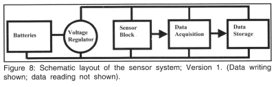
The ±70g Analog Devices accelerometer, ADXL78, requires a supply voltage of 5V. This sets the battery requirement to two 3 V lithium cell batteries in series (i.e. the voltage supply is 6V) together with a 5 V regulator. The standard filtering resistors and capacitors recommended by the ADXL78 specification sheet [8] were used. The PIC 16LF873 microcontroller from Microchip Inc. performs all the data processing and storage. This microcontroller has a built-in 10 bit analog to digital converter, which provides sufficient resolution as shown above. Thus the sensor system required no extra chips for the data acquisition; this saves on electronic real-estate area. Once the analog data is converted to a 10bit number the microcontroller sends it to on board memory storage. A logical high or low on one of the input pins of the microcontroller determines if the system would go into writing mode-data is written to the on board data bank-or reading mode. In the reading mode, the microcontroller reads the data off the storage chips and writes it to a port which connects to the serial port of a PC. It was envisioned that the first version of the sensor board would operate as follows: switch on the system; perform the drop test; acquire the data and write it to the on-board memory bank; connect the sensor board to the serial port of a PC and download the data using the RS232 protocol.
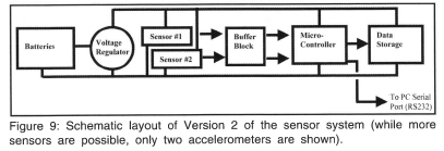
Version 1 of the sensor system was never built. Instead a new version 2, incorporating the first version and adding new features, was designed and built. In particular, version 2 allowed for three modes: data writing to the on-board data bank; data reading from the data bank; and writing the data directly to the serial port (PC) without data storage (this is referred to as the tethered mode). This was achieved by using another one of the input pins of the microcontroller: if the pin is set to logical high, the system goes into the tethered mode; a low on the pin puts the sensor system into read/ write mode depending on the first input pin's logic state.
The second major feature in version 2 was the addition of a buffer unit after the sensor system (see Figure 9). This buffer unit could be used to filter and/ or amplify the sensor data3. Version 2 also provided for future expansion of the sensor system to measure three axis accelerations (or other sensor data).
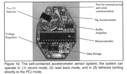
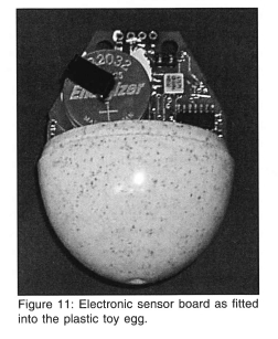
The manufactured sensor system is shown in Figure 10. Note that not all the data storage chips were incorporated on the electronics board (see the next section for details). As can be seen from this figure, the board can be miniaturized further by : (a) using a surface mount microcontroller (instead of the DIP package), and (b) populating the board on two sides. The specific shape of the board chosen was to wedge the sensor system inside the toy egg and prevent the board from moving relative to the egg (some cushioning material was also placed inside the egg for a firmer fit). In general the board can be produced in any shape. Figure 11 shows how the sensor board fits into the plastic toy egg.
Data Logging Issues
Initially the sensor system was designed to utilize EEPROM' s for the non-volatile data storage. In particular Microchip Inc.'s 24LC512 was to be used. This device is a 512kilobit (64 kilobyte) serial device that utilises standard two wire I2C communication. It allows for 8 chips to be connected to a single serial bus, thus giving 512 kilobytes of storage space. These EEPROM's require 5 milliseconds for any write operation. If data acquisition, conversion and writing are performed sequentially, the maximum throughput, ignoring all other times but the EEPROM's write requirements, will be 200 bytes/second. Since the data has to be sampled at 1000 samples/ second, EEPROMs could not be used for this application. (The EEPROM's write speed can be increased by various schemes, e.g. writing to different chips. However, these increases were not investigated.)
An alternative to the EEPROM is Ramtron Inc.'s FRAM. These devices utilize the same serial communication protocol, are pin compatible and thus can be dropped into the positions of the EEPROMs. FRAM's advantage is that there is no latency period in the write operation. Thus the required 1000 samples/ second can be met with FRAM. The main disadvantage of using FRAM is the relatively small data storage capacity. The largest serial FRAM manufactured is a 256kilobit device (the FM24C256). With a maximum of 8 devices attached to any one bus gives a storage space of 256kilobytes. The measured accelerations are 10bit numbers. These can be written to two bytes (16 bits). Although simple to implement, 6 bits, or 37.5% of the space will be wasted. An alternative would be to pack the 10bit numbers into memory across bytes utilizing a single bit to flag the start of a new measured number. The wastage in space would go down to 6.25%. For simplicity, in this version of the sensor board the former methodology was implemented.
It was estimated that several drop tests in the laboratory could be conducted within 30 seconds. Calculating the size of memory storage required for one axis accelerometer running at 1000 samples/second yields 60kilobytes. Two FRAM 256kilobit chips would give 64kilobytes of space. Thus, although the board that was manufactured provided space for four FRAM devices, only two chips were used (see Figure 10).
In summary, the sensor system has a maximum acceleration range of 10g, with a 10bit resolution, a speed of 1000samples/ second, and 32 seconds of data could be stored to non-volatile memory. Although not required for the present egg drop application, there are several areas where the performance of the sensor system can be improved.
Sensor Calibration
The accelerometer sensor system was calibrated by using the earth's gravity field. In general, accelerometers respond not only to accelerations (dynamic component), but also to the earth's gravitational field (static component). This static component cannot be separated from the total result unless some form of filtering is utilized. This filter also would effect low frequency acceleration components. The earth's gravity causes a lg offset. For a 10g accelerometer this constitutes a 1.4% error. This error was considered acceptable for the drop test experiments, and the gravitational field filtering was not implemented.
For calibration, the axis of the sensor board was aligned with gravity (+1g), ie, the sensor board was placed perpendicular to the earth, and a reading in bits was taken. The sensor board was then rotated 180° and another reading was taken (this corresponds to -1g). The one reading was subtracted from the other. The sensitivity of the sensor system is given by the subtracted value divided by 2g. To verify the sensitivity, the calibration was performed at least three times.
The sensor system sensitivity was calculated to be: 6.5 bits/g. This value compares favourably to the theoretical resolution of 7.3bits/g (see the subsection entitled "Sensor and Data Acquisition Issues" above).
The offset of the sensor system (in bits) was calculated by adding the above two readings and dividing by two. The offset was then subtracted from all the data readings.
For the sensor system the offset was calculated to be: 514bits. As expected this is approximately the mid point of the 0 to 10bit range.
To obtain the acceleration readings in terms of the earth's gravitational acceleration g, the offset was first subtracted from all gathered data. The results were then divided by the sensitivity of the sensor system.
Measurements with the developed sensor system
Description of Experiments
The test structure with the plastic egg containing the accelerometer system was used to simulate the egg drop contest. The aim was to verify the validity of the mathematical model of impact. The theory predicted maximum impact accelerations of nearly 150g when the drop height is 15meters. As explained above, all experiments were performed in a controlled laboratory environment. Thus the drop height was limited to the height of the ceiling, i.e. 3meters, which corresponded to a theoretical maximum acceleration of 67g.
Six sets of drop tests were conducted from 0.5,1.0,1.5,2.0,2.5 and 3 meters. In each experiment, the structure was first brought level with the ground before being dropped. Since the sensor board utilizes only a one-axis accelerometer, only those drop tests that produced predominantly vertical oscillations of the egg were accepted as valid. Non vertical impact was often caused by the structure starting the fall from a non level position.
Since there is 32 seconds of write time, several drop tests were performed for each recording period. The exact number of drop tests in the recording depends on how quickly each drop could be set up.
Typical results
Typical calibrated acceleration data for one recording are presented in Figure 12. This figure shows drops from four heights: 0.5,1,1.5 and2 meters.
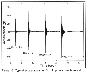
As expected, the oscillations of the egg resemble classical damped motion. Note how the maximum (negative) accelerations increase as the drop height increases. At two meters the maximum acceleration exceeds -60g. The maximum accelerations are of the same order of magnitude as those predicted by theory.
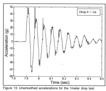
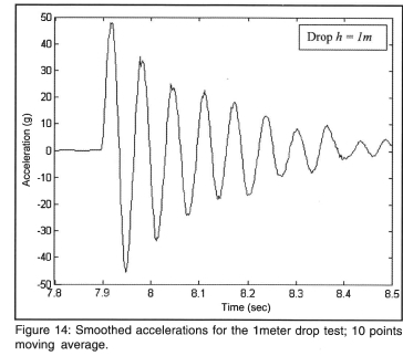
The damped oscillations can be seen in more detail in Figure 13; here an enlarged view of the 1 meter drop test is shown. This figure contains high frequency noise that can be eliminated in various ways. The approach undertaken here and in reference [1] is to perform a moving average of 10 points. This has the effect of smoothing the data (removing high frequency components) as shown in Figure 14.
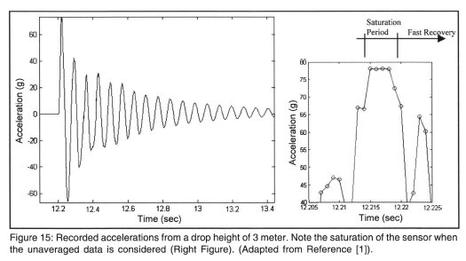
The drop tests from 3 meters revealed that the ADXL78 has a peak-to-peak range of approximately 140g. Figure 15 shows the accelerations recorded from a 3meter drop height. A lOpoint moving average is used on the data. The figure on the right, which is unaveraged, shows that saturation occurs at approximately 78g. Although accelerations greater than the nominal 70g can be measured, the accelerometer manufacturer does not guarantee the validity of these readings. Note that saturation does not cause the accelerometer to lock. This allows the sensor system to be used in general applications where the acceleration record is important and the maximum (or minimum) values beyond the nominal limits are of no interest. Since the maximum accelerations are of significance in the egg drop experiments, the structure was not dropped from higher than 3 meters.
The question of how well the theory fits the data is answered by plotting the theoretical curve (solid lines) with the experimentally measured values (dots) in Figure 16. Drop heights in these figures are 2 and 3 meters.
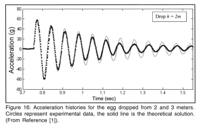
As can be seen from Figure 16, the experimentally measured data and the simplified theoretical model are in good agreement. In particular, the impact events (first peak and oscillation) are well matched. As the oscillations continue, the match between theory and experiment worsens. This could be due to: (a) the theoretical model assuming that after impact the supporting test structure is fixed to the ground- clearly this is not the case; and (b) out-of-plane motion can be occurring- the accelerometer sensor cannot account for this. If motion away from the accelerometer axis occurs, the sensor board will record the vertical component of the acceleration, i.e. an apparent reduction in acceleration. Comparing the experimental results in Figure 16, it can be seen that the 2meter drop produces oscillations that are closer to the classical damped motion. The 3meter drop on the other hand shows non-vertical accelerations (as observed visually, and as seen in Figure 16). The interested reader is referred to [1] for more detailed results and discussion.
Drawbacks and Future Work
The main drawback of the developed sensor system is that it uses only a one axis accelerometer. If the motion is not predominantly in one direction, the sensor system results will measure only the component of the acceleration that is in line with the accelerometer's axis. To solve this problem, a three axis accelerometer can be used. The architecture of the sensor board supports multiple axis accelerometers (see Figure 9). Three axis accelerometers in one integrated circuit package are available commercially, however their range is ±6g (see for example ST Microelectronics Inc LIS3L06 [9]). Clearly these devices cannot be used for the type of impacts that occur during the egg drop. Thus, two and one axis accelerometers would have to be used; the one axis would have to be mounted perpendicular to the sensor board.
Besides these difficulties, the data logging scheme would have to be revisited. The current implementation with 37.5% of the storage space wasted would not be practical. The second scheme with axis markers, described in the Data Logging Issues section would have to be implemented. To record 30 seconds of 10bit data from 3 accelerometers at 1000samples/channel/ second, as currently implemented, the amount of storage space required is 990kilobits. This includes the one bit marker that would identify the accelerometer. Four 256kilobit FRAM chips (these chips are used on the present sensor board) would give 1024kilobits of space. Thus if all four spaces in the developed sensor board were to be populated with FRAM devices, data from three accelerometers can be recorded for approximately 31 seconds.
Conclusion
This paper presented the design and research that went into developing a prototype of a one axis ±70g accelerometer. Its purpose is to measure the accelerations of a suspended egg during a drop test. The accelerometer sensor board can operate in one of two modes, depending on the setting of switches located on the board.
In the first mode, the sensor board measures the acceleration, converts the reading to a 10bit number, and stores the value to non-volatile memory. Data is sampled at 1000 readings per second. Thirty two seconds of recording is available. This time proved sufficient to carry out several drop tests for any one recording. The board is then connected to a PC, and using the serial RS232 protocol, the data is downloaded. The sensor board shape and size is custom made to fit inside a plastic toy egg to mimic the real egg drop contest.
In the second mode, the sensor board is tethered to a PC, and the 10 bit accelerations readings are written directly to the PC using the serial RS232 protocol. The memory banks are bypassed altogether.
Comparing experimental results obtained using the sensor system and theory shows that the accelerometer performs as expected. Egg drop impacts produce large accelerations. When the impact is not predominantly vertical out of plane motions of the egg occur. The sensor system records the vertical component of the acceleration only. For greater accuracy in the experiments, a two and a three axis accelerometer has to be developed. The current sensor system architecture has been designed, and implemented, to support more than one accelerometer.
Acknowledgement
The authors would like to acknowledge the help of Mr Henning and Mr Mfuko in several aspects of the egg drop contest. ZeroPoint Technologies is thanked for their technical and financial support in developing the accelerometer sensor system.
References
[1] El vin AA and Elvin NG. Developing Understanding of Dynamics in Engineering Students Through the Egg Drop Contest-Theory and Measurements, Submitted to Journal of the South African Institution of Civil Engineering, 2005.
[2] American Society of Mechanical Engineers http://competitions.asme.org/eggdrop/
[3] Case Western Reserve University http://www.cwru.edu/events/eweek/eggdrop/
[4] http://members.tripod.com/mrlewisclassroom/eggdrop.htm
[5] Chopra, AK. Dynamics of Structures: Theory and Applications to Earthquake Engineering, (2nd Edition), Prentice-Hall, 2000.
[6] CrossBow Technology Inc http://www.xbow.com/
[7] MicroStrainInc. http://www.microstrain.com/2400g-link.aspx
[8] Analog Devices Inc., Data Sheet for the ADXL78 http://www.analog.com/UploadedFiles/Data_Sheets/50606390ADXL78_a.pdf
[9] ST Microelectronics Inc., Data Sheet for LIS3L06, http://www.st.com/stonline/products/literature/ds/11669/lis3106al.pdf
1 One of the successful entrants employed an air break. Although this was explicitly prohibited the entrant was not disqualified due to the use of a novel energy dissipation mechanism.
2 Although custom-made batteries to fit any volume can be built, this was not within the budget of this project.
3 Sensor amplification was implemented in this paper to make full use of the entire voltage range of the sensor and data acquisition system.
