


Services on Demand
Journal

Article
 Article in xml format
 Article references
 Send this article by e-mail
Indicators
Related links
-
 Cited by Google
 -
 Similars in Google
Share

 Permalink
R&D Journal
On-line version ISSN 2309-8988Print version ISSN 0257-9669
R&D j. (Matieland, Online) vol.23 Stellenbosch, Cape Town 2007
Development of a Low Cost Waypoint Navigation Autopilot for an unmanned Aerial Vehicle
I.K. PeddleI; G.W. MilneII
ILecturer, Department of Electrical and Electronic Engineering, Stellenbosch University, Private Bag X1, Matieland, 7602. E-mail: ikpeddle@sun.ac.za
IIProfessor, Department of Electrical and Electronic Engineering, Stellenbosch University
ABSTRACT
This paper elicited special praise from the reviewers. Sadly, Professor Garth Milne, who played a principal role in South Africa's satellite program, was taken from us too early on 25 May 2007 (ed.)
This paper describes the development of a waypoint navigation autopilot for a small Unmanned Aerial Vehicle. The aircraft's nonlinear dynamic model is developed from first principles using only empirical and geometric data. A computationally inexpensive flight control system, based upon output feedback alone, is developed to operate with low cost commercial-off-the-shelf sensors. A novel multiple root loci design method is used to design the longitudinal multiple-input-multiple-output output feedback controller. A computationally inexpensive waypoint navigation algorithm is described. The practical implementation of the autopilot on a microprocessor based avionics package with a total cost of less than R5000 is discussed. Results from three days of flight tests verify the autopilot's practical success. The immediate success can be largely attributed to the controller architecture and the extensive simulation of the entire autopilot in the two nonlinear simulators that were developed.
Nomenclature
Roman
b Wing span
Wing mean aerodynamic chord
C( ) Non-dimensional aerodynamic coefficient function
g Gravitational force per unit mass
Ix Moment of inertia about the x body axis
Iy Moment of inertia about the y body axis
Iz Moment of inertia about the z body axis
Ixz XZ cross product of inertia
L Roll moment coordinate in body axes
m Mass of the aircraft
M Pitch moment coordinate in body axes
N Yaw moment coordinate in body axes
P Roll rate coordinate in body axes
PN North displacement in inertial axes
PE East displacement in inertial axes
PD Down displacement in inertial axes
q Dynamic pressure
Q Pitch rate coordinate in body axes
R Yaw rate coordinate in body axes
S Wing area
TThrust function
UAxial velocity coordinate in body axes
VLateral velocity coordinate in body axes
VVelocity vector magnitude
WNormal velocity coordinate in body axes
XAxial force coordinate in body axes
VLateral force coordinate in body axes
Z Normal force coordinate in body axes
Greek
αAngle of attack
α0 Trim angle of attack
ß Angle of sideslip
δA Aileron control variable
δE Elevator control variable
δR Rudder control variable
δT Throttle control variable
φ Roll angle of Euler 3-2-1 set
Θ Pitch angle of Euler 3-2-1 set
Ψ Yaw angle of Euler 3-2-1 set
1. Introduction
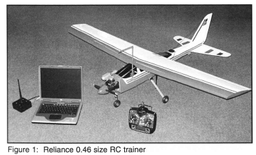
Unmanned aerial vehicles (UAVs) have been used throughout the world for various missions including intelligence, surveillance and reconnaissance (ISR) since the 1960s. South Africa's major contributions to UAVs are the Seeker family, designed by Denel Aerospace, and the advanced technologies and engineering (ATE) designed Vulture. Motivated by the desire to contribute to this fast growing field of research, the Department of Electrical and Electronic Engineering at Stellenbosch University formed a UAV research group in 2001. This paper describes the results of two years of work on the research group's first fixed wing radio controlled (RC) aircraft: a Reliance 0.46 size trainer shown in figure 1. The objective of the two year project was to design and validate a waypoint navigation autopilot while keeping the cost, weight and power consumption of the solution low.
Design of the autopilot began with the development of a nonlinear aircraft model that was used as a basis for simulation and control system design. The model was developed using only empirical and geometric data for the aircraft. The nonlinear model was linearised about a level flight trim condition and a set of decoupled controllers were designed to regulate the variables of interest. The control system architecture employed played a key role in allowing the design objectives of the autopilot to be met. A computationally inexpensive navigation algorithm was developed to make on-board waypoint navigation possible. The control system and navigation algorithm were embedded onto a custom made, low cost avionics package. Before commencing with flight tests, extensive nonlinear simulation of the autopilot was conducted for risk reduction purposes. Three days of flight tests were then held to practically verify the autopilot. The sections that follow provide the details of the design process described above.
2. Modelling
The aircraft is modelled as a six degree of freedom rigid body with aerodynamic, thrust and gravitational forces and moments acting upon it. The limited flight range and low translational velocity of a RC aircraft justify the use of a non-rotating, flat earth inertial reference frame. Body axes are used to simplify the equations of motion, which are provided below as a function of the body-axis-coordinated force and moment vectors. Note that it has been assumed that the x-z plane coincides with the aircraft's plane of symmetry and the origin coincides with the aircraft's centre of mass. Standard notation is used1,2.
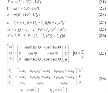
Equations 2.1 to 2.6 describe the kinetic relationship between the forces and moments acting on the aircraft and its change in momentum. Equations 2.7 and 2.8 describe the attitude and position dynamics respectively. Note that the attitude dynamics are parameterised by Euler 3-2-1 angle, an acceptable parameterisation given the flight envelope of the aircraft.
Expanding the force and moment terms in equations 2.1 to 2.6, it is noted that the aerodynamic forces are by far the most complex to model. However, the aerodynamic model takes on its simplest form when the body axis system is chosen as stability axes3. Given that the scope of this paper extends only to the development of an autopilot for flight about a nominal trim condition, it is beneficial for the sake of simplicity to work with stability axes from the start. Note that once a specific trim condition has been chosen, the stability axes remain fixed with respect to the aircraft and all inertial and geometric properties can be converted to stability axes using standard transformations3.
The aerodynamic model was developed using empirical equations and the geometry of the aircraft. Empirical equations were used to model the lift and drag of each aerodynamic surface as a function of its local angle of incidence. The aircraft geometry was used to determine the induced incidence angles as a function of the aircraft's gross motion variables and to determine the total forces and moments about the centre of mass. Four major aerodynamic surfaces were identified and modelled. These were the wing, tailplane, fin and fuselage. It was assumed that the wing produced both lift and drag, the tailplane and fin produced only lift (relative to their local orientation) and the fuselage produced only drag. Empirical equations for the lift and drag of an airfoil as a function of its local airflow velocity vector and the airfoil geometry were obtained from Cook3 and Schevell4.
The aircraft's propeller engine was modelled as a source of constant power at a given throttle setting4 with a first order lag response to throttle changes. This model was chosen because it adequately captures the thrust dynamics of a standard RC engine. Finally, the limited flight range of the aircraft promoted the use of a constant force per unit mass gravitational model.
The total force and moment model is provided in abbreviated form below. Only the structure of the aerodynamic and thrust models has been provided with functional dependencies listed in parenthesis. For details on the full aerodynamic and thrust models see Peddle2.
3. Control System Design
The design goals in creating the autopilot were to keep the cost, weight and power consumption low while creating an autopilot that was fundamentally sound and easily transferable to other airframes. The aircraft was to be capable of autonomous waypoint navigation within a conventional flight envelope. This specification requires the regulation of a number of motion variables for which a myriad of control strategies exist5-8. The following section discusses the architecture of the autopilot designed in this project and highlights the fundamental problems associated with low cost flight control.
3.1 Control system overview
The control system should be capable of regulating the motion variables of interest in the presence of disturbances such as wind, changes in inertial parameters with time and modelling imperfections. Feedback control is well suited to this task as it is capable of both reducing the sensitivity of the system to modelling uncertainties and providing disturbance rejection to those quantities which detract from the desired aircraft motion. However, inherent in the concept of feedback control is the requirement for sensors, whose signal quality directly influences the performance of the closed loop system. Due to the autopilot cost and size considerations, it was decided to limit the choice of sensors to small, low cost, commercial-off-the-shelf (COTS) units. In turn, the architecture of the control system was specifically designed to minimise the adverse effects introduced by low cost sensors. Three distinct levels of control were identified and are discussed in order of decreasing bandwidth below.
Stability Augmentation: The purpose of control at this level is to provide high bandwidth artificial damping and thus remove energy from any high frequency modes of motion present, including un-modelled modes. By doing so, the augmented aircraft presented to the second level of control will have greatly improved stability characteristics and far more predictable dynamics. Stability augmentation can easily and cost effectively be achieved by feeding back the signals from inertial angular rate sensors to the respective aerodynamic actuators. Apart from the extra damping provided by this feedback strategy, inertial rate feedback provides damping with respect to inertial space as opposed to damping with respect to the airflow as the aerodynamic surfaces do. Thus, the damping is effective at rejecting disturbances from wind gusts and thus improves the overall disturbance rejection capabilities of the airframe.
Attitude Regulation: The fundamental control task in automating the flight of an aircraft is to regulate its attitude. Attitude regulation in effect controls the acceleration of the aircraft, which integrates over time into velocity and position. Consequently, if the attitude can be kept under control, then simple successive loop closures about the velocity and position states can be used to further control the aircraft.
However, the major obstacle with attitude regulation in UAVs with size and cost design constraints is the lack of a suitably accurate attitude sensor. As a result, a number of methods have been developed to either estimate attitude using other more readily available low cost sensors9-11, or to design controllers that regulate attitude indirectly1 i.e. through other motion variables that in turn constrain the attitude. The latter option was adopted in this project based on the fact that attitude estimation can become a computationally expensive process and thus violate the low processing power design constraint.
To control attitude indirectly it was noted that in conventional flight, controlling the airspeed and climb rate will automatically regulate the pitch angle. Also, for a fixed wing aircraft, the roll angle in a steady state turn (under small roll angle assumptions) is approximately linearly related to the aircraft's inertial yaw rate2. The obvious advantage in controlling these motion variables over the attitude angles directly is that low cost sensors are readily available in the form of absolute and differential pressure sensors and angular rate gyroscopes.
Trajectory Control: With the attitude regulated, the trajectory controllers are then merely responsible for the regulation of the velocity and position vectors over time. This regulation takes place via the attitude controllers. Making use of this architecture essentially allows the trajectory controllers to be designed independently of the aircraft. The trajectory motion variables of concern in this project were the altitude, heading and cross track error. Measurements of these quantities are easily provided by an absolute pressure sensor and a low cost global positioning system (GPS) receiver and the control systems required involve simple, computationally inexpensive feedback laws.
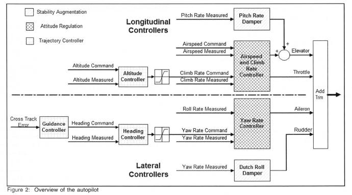
A block diagram overview of the autopilot used in this project is shown in figure 2. The autopilot is based on the layered architecture described above with the various layers colour/ shade coded. Longitudinally, the pitch rate damper contributes on the level of stability augmentation. The airspeed/climb rate controller indirectly regulates the pitch angle and the altitude controller serves as the longitudinal trajectory controller. Laterally, the Dutch roll damper provides control on a stability augmentation level. The yaw rate controller in effect regulates the roll angle of the aircraft while both the heading and the cross track error controllers perform lateral trajectory control. The only sensors required for the autopilot are three rate gyroscopes, an absolute and differential pressure sensor and a standard GPS receiver, all of which are available commercially at low cost.
Since the control task was limited to automatic flight within a conventional flight envelope, each of the controllers of figure 2 was designed as a linear controller about a straight and level flight trim condition. This strategy allowed the use of the many powerful analysis and design tools available within the field of linear systems theory. The subsections that follow discuss some of the more important details of each of the controllers of figure 2.
3.2 Controller details
Pitch Rate Damper: This controller simply feeds the signal from a pitch rate gyroscope back to the elevator. The main design considerations are to provide sufficient damping of the short period mode as well as to provide sufficient pitch stiffness with respect to inertial space.
Airspeed/Climb Rate Controller: Controlling the airspeed and climb rate using the elevator and throttle constitutes a multiple-input-multiple-output (MIMO) problem. Standard control system tools such as the linear quadratic regulator (LQR) are available for MIMO control system design and use the extra degrees of freedom in the control problem to minimise a cost function quantifying the tradeoffs involved between control usage and state deviation. The LQR also provides inherent robustness properties12 further increasing its attractiveness as a solution.
A LQR design does however require the full state vector to be available for feedback. In the scenario where the full state vector cannot be directly measured, an estimator is typically used. However, using an estimator not only increases the complexity of the controller, but also negates the inherent robustness properties of the LQR design12. Furthermore, central to the accuracy of the estimated state vector is the accuracy of the measurements and the accuracy of the model. Since in this project the model was derived using empirical and geometric data, it was expected that it would be of a low fidelity. This fact together with measurements from low cost sensors further motivated the decision to avoid an estimator.
By ruling out the use of an estimator, output feedback was left as the only option, since low cost sensors were not available to measure the entire state vector. However, output feedback is an attractive option since it yields a simple controller whose feedback gains are often more intuitive (and thus easier to practically fine tune) than those of state feedback. A Proportional-Integral (PI) output feedback controller was selected. The integration term was included to make the longitudinal system insensitive to steady state disturbances arising for example from discrepancies between the actual and modelled longitudinal static aerodynamic coefficients.
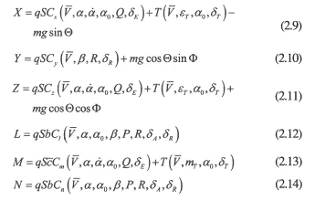
A novel iterative multiple root loci method was employed to design the output feedback controller. Here, the nominal poles of the system under the PI control law were plotted and then the root loci corresponding to a variation of each one of the feedback gains were plotted on the same axes. The multiple root loci were then analysed and a decision made as to which single gain to change by a small amount such that the closed loop poles moved closer to the desired region in the s-plane. With the gain updated, the new nominal poles were then plotted and the process repeated until a satisfactory design was achieved. Although the design procedure involved a fair amount of iteration and engineering judgement, it was capable of producing a satisfactory MIMO output feedback controller. Figure 3 shows the multiple root loci at the end of the MIMO design procedure. The loci were colour and shape coded so that a particular feedback gain could be quickly identified. Root loci drawn with crosses represent feedback to the throttle while root loci drawn with dots represent feedback to the elevator. The colours blue, green, red and black represent feedback from airspeed, climb rate and the integral of the errors in those two signals respectively. The two solid lines represent the damping and natural frequency constraints for the closed loop system.
Altitude Controller: The altitude controller is responsible for accepting a barometric altitude command and generating a climb rate signal such that the altitude is regulated. The presence of a natural integrator in the altitude dynamics promoted the used of a simple proportional feedback controller with a saturating climb rate command. The saturation effectively breaks the altitude controller's feedback loop when the commanded climb rate signal saturates (since the forward gain is then zero) and ensures that the aircraft enters a constant maximum climb rate mode at those times. This typically occurs when large altitude step commands are issued.
Dutch Roll Damper: The purpose of the Dutch Roll damper is to suppress the typically lightly damped Dutch Roll mode of the aircraft and provide damping with respect to inertial space. This is achieved in a standard manner1, by feeding a washed out yaw rate signal back to the rudder. The washout filter ensures that the Dutch roll damper does not counter the constant yaw rate experienced during steady turns. The washout filter cut-off frequency is thus selected to ensure adequate rate feedback at and around the frequency of the Dutch roll mode.
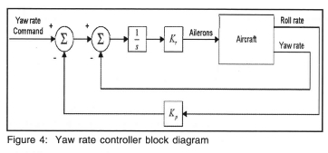
Yaw Rate Controller: In a steady state turn at low bank angles the yaw rate of the aircraft is well approximated as being linearly related to the roll angle. Thus, the concept behind the lateral attitude controller is to feed back yaw rate to the ailerons instead of an estimated roll angle. An advantage of this strategy is that significantly fewer calculations are required since no estimation takes place.
It was desired to implement an integral type controller to ensure that the commanded yaw rate could be tracked with zero steady state error even when subject to constant steady state disturbances such as those due to asymmetry in the actual aircraft. However, it was found that the stability of the yaw rate controller could be greatly improved by simply feeding roll rate back to the ailerons too. An intuitive explanation for this is that because the ailerons do not directly produce a yaw rate, the controller will have the tendency to wind up the aileron command in an attempt to achieve the desired dynamic response. Feedback of the roll rate signal compensates for this by reducing the yaw rate command during the transient phase of the turn, while playing no part when the roll rate is zero during the steady state. The block diagram of figure 4 illustrates the yaw rate controller which is in fact simply one of the yaw orientational control systems described in Blakelock1.
Heading Controller: The heading controller is the lateral counterpart of the altitude controller. It is responsible for converting a heading error signal into a yaw rate command (note that ground track heading is regulated, not magnetic heading). A simple proportional feedback controller was used since the natural integrator present in the heading dynamics ensures a zero steady state tracking error when no steady state disturbances are present. However, the rate gyroscopes used in the yaw rate controller can exhibit biases, which would result in steady state heading errors. Upon further analysis it was found that these errors would be small (less than 5°) for representative gyroscope biases and thus did not warrant the added design effort involved with the inclusion of a compensator integrator. The controller was designed in the discrete time domain due to the fact that GPS heading updates were only available at 4 Hz.
Cross Track Error Controller: This controller is responsible for regulating the lateral path error by commanding an appropriate heading. A simple proportional controller was used. This controller was also susceptible to the yaw and roll rate gyroscope biases in the steady state. However the typical errors were small (less than 5 m) and thus the added effort of including an integrator into the compensator was not warranted. Note however that the steady state error problems of both the heading and cross track error algorithms could be solved by the inclusion of a single integrator term into the heading compensator alone. The cross track error controller was also designed in the discrete time domain due to the 4 Hz GPS position updates.
4. Navigation Algorithm
The specifications stated that the autopilot was to be capable of autonomous waypoint navigation. The cross track error trajectory controller designed in the previous section is capable of guiding the aircraft to follow a given lateral path. It is the task of the navigation algorithm however, to calculate a flyable path from one waypoint to the next (path planning), and then from this path and the current aircraft location, to calculate the cross track error. For the purposes of this project, a waypoint was defined as a structure containing a three dimensional location, a heading and a velocity. Some of the more important details regarding the path planner algorithm are discussed below.
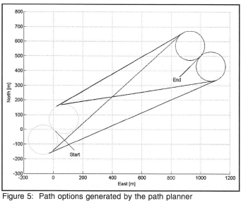
Since the waypoint navigation algorithms were to be run onboard the aircraft, it was desired to create a computationally efficient path planner. A simple strategy of creating a trajectory made up from a circular path tangent to the initial heading, a straight line segment and a circular path tangent to the final heading was adopted. A typical example of the path options generated from one waypoint to the next is shown in figure 5. The shortest path begins at the start point (0 m N, 0 m E), turns out right and departs on the first tangent, to eventually meet the right turn approach circle that leads to the end point(500 mN, 1000 m E). The other three path options would be discarded by the path planner. In the most common case, four path options are generated and the path planner selects the one with the shortest distance. The path planner code was capable of being executed in approximately 20 ms on an 8 bit, 14 MHz microprocessor.
5. Simulation
Simulation played an extremely important role in reducing the potential cost of flight tests and increasing the chances of practical success in the project. Apart from the linear simulations conducted during the design phase of each of the controllers, two complete nonlinear simulators were created to thoroughly test the autopilot before practical flight testing began. One of the simulators was a Simulink-based block diagram simulator while the other was a graphical simulator written in C, using OpenGL for the three-dimensional visualisation. Both simulators included the nonlinear aircraft model, the autopilot, the control microprocessor model (e.g. models of quantization due to the fixed point arithmetic and due to the conversions between the analogue and digital worlds) and the sensor, actuator and wind models.
The Simulink-based simulator served as the primary debugging tool because of the intuitive feel provided by the structured nature of the simulator. The major advantage of the graphical simulator was its visual interface which allowed the designer to actually see the controllers at work and notice effects such as longitudinal and lateral cross coupling in a three-dimensional environment. A whole host of potential practical problems were evaluated using the two simulators, including topics such as autopilot smooth transition, autopilot code preparation, effects of quantization and effects of wind and sensor noise.
6. Implementation
A low cost avionics package was created to practically implement the autopilot. Figure 6 shows a block diagram overview of the avionics and ground station.
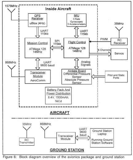
At the heart of the avionics package were two 8 bit, 14 MHz microprocessors. The microprocessor named Flight Control was responsible for executing all of the control algorithms at 25 Hz (except the heading and cross track error controllers which ran at 4 Hz). The microprocessor named Mission Control was used primarily to interface with the GPS and radio frequency (RF) communication modules as well as to execute the navigation algorithms. The use of two microprocessors provided a means with which to implement the logical split between the high and low bandwidth operations of the avionics package. It also provided enough peripheral ports to interface with the sensors, communication modules and servos. The sensors and communication modules were all off-the-shelf devices and the radio controlled equipment was standard.
Custom ground station software was written to provide a graphical user interface to the autopilot. The software made it possible to view all of the autopilot telemetry as well as update parameters such as controller gains and waypoints in flight. Thus, the ground station provided an excellent platform from which to practically debug the autopilot. The total cost of the avionics package was less than R5000, it weighed 850 g (including the housing, battery pack and pitot and static ports) and consumed 2.5 W of power.
7. Flight Test Results
After the controllers had been thoroughly simulated, three successful days of flight tests were held which culminated in the aircraft performing autonomous waypoint navigation as initially desired. All practical results agreed extremely well with those predicted by simulation. The lack of complications during the flights tests can be largely attributed to the well thought out controller architecture and the vast amount of simulation conducted beforehand.
Figure 7 shows typical longitudinal data collected over an entire test flight. The aircraft was under pilot control for the first 195 s after which the autopilot was armed with an airspeed command of 25 m/s and an altitude command of 100 m. With the autopilot armed, the RMS error in airspeed was 0.86 m/s (3.44 %) while the RMS error in altitude was 1.38m (1.38%). Note that these errors are based on sensor measurement data and thus include the errors due to sensor noise. Furthermore, changes in the aircraft's heading during the flight account for some of the noise seen on the response plots. The autopilot was disarmed after 477 s and the aircraft landed by the pilot.
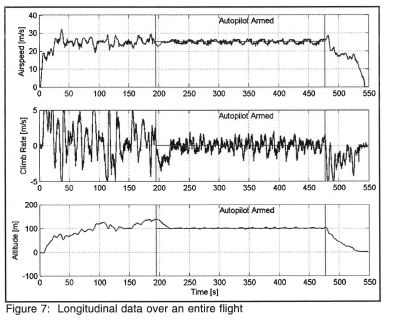
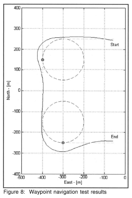
Figure 8 shows the performance of the aircraft during waypoint navigation. The small dots in the figure mark the waypoints and the dashed lines show the planned circular and straight line paths. The solid line indicates the actual path flown by the aircraft. The aircraft is seen to track the desired trajectory although the tracking accuracy during the circular part of the course is poor. The poor tracking of the circular paths can be attributed to the nature of the cross track error controller. As discussed in section 3, a simple proportional feedback controller was used. This type of controller provides good asymptotic tracking of straight line trajectories but fails to track circular trajectories with zero steady state error due to the requirement of a non-zero yaw rate. This problem can be overcome in a number of ways, including feeding the required turn rate forward to the yaw rate controller, adding integrators to the compensator, or using a nonlinear guidance law5.
8. Conclusion
This paper has described the development of a waypoint navigation autopilot for a small UAV. The control system was designed specifically to work with low cost commercial-off-the-shelf sensors and required very little computational power. A navigation algorithm capable of running onboard a microprocessor based avionics package was also developed. The benefits of a well thought out control architecture and extensive simulation were illustrated by the practical success of the autopilot in only three flight test days.
Stellenbosch University's UAV research group continues to make steady progress. Projects involving automatic takeoff and landing, automatic aerobatic flight control, path planning, flight control of radio controlled helicopters, ducted fan control13 and UAV certification and regulation14 are currently underway. The simulation tools developed in this project have been extended to bring together the convenience of the Simulink-based block diagram simulator and the visual advantages of the three-dimensional graphics simulator, by creating a three-dimensional graphics sink block for Simulink. The simulator and avionics package have also been extended to cater for hardware in the loop simulation. The continuous development of the autopilot design tool chain is of the utmost importance in maximising the chances for success and minimising the risks involved in future projects. For further information on all UAV projects at Stellenbosch University see http://esl.ee.sun.ac.za/ or the authors' personal webpages.
9. Acknowledgements
The authors would like to thank Denel Aerospace and the National Research Foundation's THRIP program for funding the project. The Helderberg Radio Flyers club is acknowledged for allowing us the use of their facilities for flight tests. The steady hands of our safety pilot, Dr Kas Hamman, were greatly appreciated during the flight tests.
References
1. Blakelock JH, Automatic Control of Aircraft and Missiles. Wiley-Interscience, 2nd edition, 1991.
2. Peddle IK, Autonomous Flight of a Model Aircraft, MSc Eng thesis, University of Stellenbosch, 2005. [ Links ]
3. Cook MV, Flight Dynamics Principles, Elsevier Butterworth-Heinemann, 1997.
4. Schevell RS, Fundamentals of Flight, Prentice-Hall, 1983.
5. Park S, Avionics and Control System Development for Mid-Air Rendezvous of Two Unmanned Aerial Vehicles, PhD dissertation, Massachusetts Institute of Technology, February 2004. [ Links ]
6. De La Parra S and Angel J, Low cost navigation system for UAV s, Aerospace Science and Technology, September 2005. 9 (6), 504-51. [ Links ]
7. Kingston D, Beard R, McLain T, Lar sen M and Ren W. Autonomous vehicle technologies for small fixed wing UAVS. AIAA 2nd Unmanned Unlimited Systems, Technologies and Operations-Aerospace, Land and Sea, Conference and Workshop & Exhibit, San Diego, CA, September 2003, AIAA Paper No. 2003-6559.
8. Tunik AA and Galaguz TA, Robust stabilization and nominal performance of the flight control system for small UAV, Journal of Computational and Applied Mathematics, 2002, 1 (2), 34-45. [ Links ]
9. Kingston DB, Beard RW, Real-time attitude and position estimation for small UAVs using low-cost sensors, AIAA 3rd Unmanned Unlimited Systems Conference and Workshop. Chicago, II, September 2004, AIAA Paper No. 2004 -6488.
10. Bryson M and Sukkarieh S, Vehicle model aided inertial navigation for a UAV using low-cost sensors, Australian Conference on Robotics and Automation, Canberra, Australia, 6 - 8 December, 2004.
11. Park S and How J, Examples of Estimation Filters from Recent Projects at MIT, Advanced estimation for GPS and inertial navigation - 16.324, Massachusetts Institute of Technology, Open Courseware, 2004.
12. Franklin GF, Powell JD and Emami-Naeini A, Feedback Control of Dynamic Systems, Prentice Hall, 4th edition, 2002.
13. Heise R, Peddle IK, Jones T and Milne GW, SLADE: Development of a UAV decoy, 32nd European Rotorcraft Forum, Maastricht, Netherlands, 12 - 14 September 2006.
14. Ingham L, Jones T and Maneschijn A, Certification of unmanned aerial vehicles in South African airspace, SAIMechE R&D Journal, March 2006, 22 (1), 21-27. [ Links ]
Received 11 March 2006
Revised form and accepted 11 June 2007
