


Services on Demand
Journal

Article
 English (pdf)
 Article in xml format
 Article references
 Send this article by e-mail
Indicators
Related links
-
 Cited by Google
 -
 Similars in Google
Share

 Permalink
R&D Journal
On-line version ISSN 2309-8988Print version ISSN 0257-9669
R&D j. (Matieland, Online) vol.24 Stellenbosch, Cape Town 2008
An Overview of SO2 Emissions Reduction Techniques
Z.O. Siagi; M. Mbarawa
Department of Mechanical Engineering, Pretoria Campus. Tshwane University of Technology. Private Bag X680. 0001 Pretoria, South Africa. siagiz@tut.ac.za
ABSTRACT
Coal is the primary source of energy produced and consumed in South Africa. Coal combustion results in the production of SO2, a precursor of acid rain. As South Africa adopts and enforces emission limits, it will become mandatory for power plants to befitted with SO2 scrubbers. This paper presents an overview of commercially available flue gas desulphurization (FGD) technologies that have an established record of performance. The paper assesses the application of these technologies and their performance in the SO2 emissions reduction.
Additional Keywords: SO2, Desulphurisation, Emissions
1. Introduction
The electricity sector plays a pivotal role in the South African economy. Its post-apartheid importance lies in its role not only as a key input to industrial development, but also in improving the quality of life for the previously disadvantaged majority. South Africa's generating technology is based largely on coal-fired power stations, mostly concentrated near and to the east of Johannesburg - close to the main coal mining areas as well as the major demand centre. At the end of 1999, there were 49 power stations in the country, of which 20 were coal-fired accounting for 90 per cent of the total capacity of 43 142 MW (excluding capacity in reserve and under construction)1. The only non-coal stations are the Koeberg nuclear station (four per cent) and three pumped storage facilities (also four per cent). On combustion, the sulphur contained in the fuel is converted to SO2. Coal combustion is the single largest manmade source of SO2 accounting for 50 % of the annual global emissions2.
SO2 is a colourless, nonflammable gas with a penetrating odour that irritates the eyes and air passages. A one-hour exposure to a SO2 concentration of 10 ppm can cause breathing problems3. The effects become much more serious when SO2 is combined with particulates and enters the digestive system, a phenomenon known as the "cocktail effect". Research has shown that exposure for asthmatics is significantly more damaging than for normal subjects and even moderate concentrations may result in a fall in lung function in these cases. According to a 1999 World Bank study in India, air pollution was responsible for 40 000 premature deaths, 17 million respiratory hospital admissions and 1.2 billion restricted activity days4. In addition to the health effects, moderate to high levels of SO2 contribute to acid rain. Acid rain causes decimation or deformation of aquatic life in streams and lakes. Additionally, it leads to damage of trees and agricultural crops and degradation or destruction of bridges, buildings, and monuments. Airborne SO2 and its derivatives can also contribute to reduction of visibility due to formation of a haze. In view of these health and environmental considerations, the control of SO2 emissions is desirable. The South African Government is committed to providing reasonable measures for the prevention of pollution and ecological degradation. According to an environmental act5 signed into law in 2005, ambient concentrations of sulphur dioxide (SO2) may not exceed:
□ A ten-minute average instant peak of 0.191 ppm measured at S.T.P.
□ An instant peak of 500 μg/m3 measured at STP.
□ A 24-hour average of 0.048 ppm or 125 μg/m3 measured at S.T.P.
□ An annual average of 0.019 ppm or 50 μg/m3 measured at S.T.P.
Sulphur dioxide emissions reduction techniques can be categorized into three groups 1) pre-combustion techniques, 2) combustion techniques, and 3) post-combustion techniques.
1.1 Pre-combustion technologies
Fuel switching and coal cleaning are two pre-combustion techniques. Some power plant designs allow for fuel switching; for example, a natural gas-fired power plant may utilize oil as an auxiliary fuel. Similarly plants which burn wood waste may use coal to ensure base load operations. Table 1 shows typical emissions from different technologies using different fuels6.
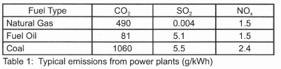
Switching from a high sulphur coal to a low sulphur coal or blending a low sulphur coal with a coal of inferior quality may result in a fuel whose emissions could be within allowable limits. The appropriate coal quality, however, has to be considered with regard to other pollutants because a decrease in SO2 emissions may cause an increase in NOx or fly ash7.
Coal may be cleaned by physical, chemical or biological means. Sulphur is present in coal in two inorganic forms, these being pyritic sulphur (FeS2) and sulphates (Na2SO4, CaSO4, FeSO4) and as organic sulphur. Unless the chemical bonds that hold the sulphur are broken or the organic sulphur compound is extracted, organic sulphur cannot be removed from the coal. Therefore, the amount of organic sulphur present defines the lowest level to which a coal may be cleaned using physical methods. Biological processes theoretically offer the potential of totally removing sulphur near ambient conditions and with low energy requirements. Biological desulphurisation is attractive because it operates at close to ambient temperatures and involves no associated loss of coal carbon8.
1.2 Combustion technologies
There are several technologies which results in improved thermal efficiency and reduced sulphur emissions. These include: bubbling fluidized bed combustion (BFBC), circulating fluid-ized bed combustion (CFBC), and pressurized fluidized bed combustion (PFBC); Integrated gasification combined cycle (IGCC) and combined cycle gas turbine (CCGT). Fluidized bed combustion (FBC) is a technology for burning hard and brown coal, but it can also burn other solid fuels such as petroleum coke, and low grade fuels such as waste, peat and wood. The use of calcium-based sorbents, such as limestone or dolomite, in fluidized bed combustion of coal to reduce sulphur dioxide emissions is a well established technique9. Limestone is introduced into the fluidized bed combustor within the temperature range 750-900°C, the limestone is rapidly calcined to the porous calcium oxide, which can subsequently react with SO2 to form calcium sulphite and calcium sulphate. Emissions can be further reduced by integrated combustion control in the system due to the addition of lime/limestone to the bed material. The IGCC is based on the transformation of coal into synthetic gas. After the gasification stage, the gas is cleaned by means of water and absorption dissolvers. Thus an IGCC plant has significantly lower emissions of SO2, NOx, and particles than standard coal-fired power plants. However, the units for gasification, purification, and other auxiliary systems raise the initial capital outlay and imply higher operational costs10. This technique can reach limit values of 200 mg/m3 or 1.7 g/kWhe with coal of 1 % sulphur.
1.3 Post-combustion technologies
Flue gas desulphurization is one of the post combustion techniques used in reducing SO2 emissions. Almost all commercial FGD processes are based on the fact that SO2 is acidic in nature, and remove the SO2 from flue gases by reaction with a suitable alkaline substance. The most commonly used alkaline materials are limestone (calcium carbonate), quicklime (calcium oxide) and hydrated lime (calcium hydroxide). Limestone is an abundant and therefore relatively cheap material and both quicklime and hydrated lime are produced from limestone by calcination. Other alkalis sometimes used include sodium carbonate, magnesium carbonate and ammonia.
2. Flue Gas Desulphurisation (FGD) Technologies
The major FGD processes can be classified as:
□ Wet Processes: included here are the limestone gypsum, seawater washing, ammonia scrubbing, the Wellman-Lord processes, biological desulphurization, and magnesium enhanced lime,
□ Semi-dry Processes: Includes the circulating fluidized bed, and sorbent spray dry; and
□ Dry Processes: includes furnace sorbent injection, induct sorbent injection, and sodium bicarbonate injection
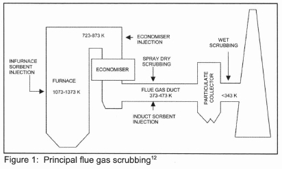
Worldwide, by 2000, there were 678 FGD systems operating on a total capacity of 229 GWe11. Approximately 79 % of the units, representing 199 GWe of capacity, are based on lime or limestone wet scrubbing and 18 % of the units, or about 25 GWe, utilize either sodium based or lime slurry (spray) dry scrubbing. Figure 1 shows the principal FGD techniques and their location in the overall power plant scheme.
2.1 Wet FGD processes
Wet FGD scrubbers are the most widely used FGD technology for SO2 control in the world accounting for about 84 % of the total capacity of all desulphurisation methods7. Many FGD systems are operating successfully at many coal-fired power facilities ranging in size from less than 100 MW to 1000 MW. They can achieve SO2 removal efficiencies as high as 99 %. Calcium, sodium, and ammonia-based sorbents have been used in a slurry form, which is injected into a specially designed vessel to react with the SO2 in the flue gas. The preferred sorbent in operating wet scrubbers is limestone followed by lime. The chemical reaction which occurs with a limestone sorbent can be expressed in a simple form as:

In practice, air in the flue gas causes some oxidation and the final product is a wet mixture of calcium sulphate and calcium sulphite. In a wet FGD employing forced oxidation, in situ or ex situ (in the scrubber or in a separate reaction chamber), the overall reaction is given by:

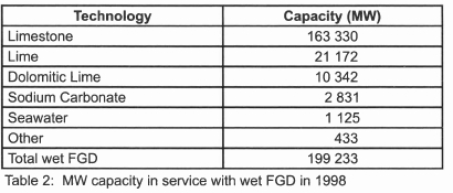
resulting in solid gypsum which has found commercial use in wallboards, cement, and plaster13. According to Danish and other European standards, gypsum normally must contain less than 3-4 wt % residual limestone to be marketable14. A variety of scrubber designs have been developed depending on how the gas and sorbent slurry are brought into contact. Four main types of wet scrubbers are available: the spray scrubber, the packed tower, the jet bubbling reactor, and the double loop reactor13. Breakdown capacity in service with wet FGD technology is given in table 215.
2.1.1 Limestone gypsum process
In the limestone gypsum wet scrubbing process, the flue gas is treated with limestone slurry in order to remove the SO2 and neutralize it. The final product is calcium sulphate dihydrate (gypsum). This is the most common FGD process now being installed worldwide, and has evolved over the last 30 years. Nowadays, a plant would normally be designed to achieve a high quality gypsum product, which is suitable for wallboard manufacture. As mentioned earlier there are a number of process variants and equipment arrangements which can be adopted. An advanced flue gas desulphurisation demonstration unit at the Bailly Generating station of Northern Indiana Public Service Company (NIPSCO) achieved a maximum removal efficiency of 98 % using coals having sulphur contents between 2.25 % and 4.5 %16. The availability of the system was high at 99.5 % over a three year period thereby eliminating the need of a spare module. The limestone gypsum process is the most well-developed and widely adopted FGD process worldwide, and is normally adopted for large power stations. The total worldwide installed capacity is approximately 149 000 MWe for coal-fired plant alone17.
The SO2 removal efficiency of FGD plants using CaCO3 as sorbent can be improved by the addition of various organic acids18. These include adipic acid, dibasic acid (DBA), formic acid, glutaric acid and succinic acid. In a wet limestone scrubber demonstration project at the Milliken Power Station, Lansing New York, the SO2 removal efficiency increased from 83 % without formic acid to 95 % with formic acid. At the same removal efficiency, using formic acid results in a 75 % reduction in energy required for circulating the sorbent slurry16. A jet bubbling reactor has also been successfully demonstrated at Georgia Power Company's Plant Yates. This plant, rated at 100 MWe, burns coal with a sulphur content ranging from 1.2 % to 4.3 %. It had a limestone utilization greater than 97 % and achieved a SO2 removal efficiency of 98 % when burning 2.2 % sulphur coal and about 95 % with 3.5 % sulphur coal16.
2.1.2 Sea water scrubbing (SWW) FGD process
Sea-water washing is an economical alternative forplants located near the coast. The sea-water washing (SWW) process uses untreated sea water to scrub the flue gas, taking advantage of sea water's natural alkalinity in order to neutralize the SO2. When SO2 comes in contact with seawater, there is a fast and efficient reaction between the SO2 and calcium carbonate in the sea water to form calcium sulphate and CO2. The reaction neutralizes the acidity of SO2 and consumes some of the buffering capacity of the seawater. The reaction is complete in a very short time, so the equipment to bring the flue gas and the seawater in contact can be compact. As a final product, dissolved sulphate ions are obtained, which are already contained in the sea water as a natural constituent. After scrubbing, the water used is treated with air to reduce its chemical oxygen demand and its acidity, and is then discharged back to the sea19. In all applications of the SWW process on power plant, raw seawater is obtained from the steam turbine condenser outlet. SWW is a rapidly expanding Technology, particularly in tropical countries. There are two major suppliers of SWW units; Lurgi Lentjes Bischoff (LLB) and Asea Brown Boveri (ABB). ABB has built 21 plants with a total installed capacity equivalent to 2 470 MWe. LLB is currently commissioning two 660 MWe plants in Indonesia17. Its main advantage is that it requires no solid sorbent as a reagent, unlike nearly all other FGD processes. The plants design is relatively simple and the only obvious disadvantage is that it is limited to use at coastal sites. The process is capable of very high SO2 removal (up to -97-98 %)17, but only if the fuel sulphur content is below 2.5-3.0 wt %. After an evaluation of various FGD technologies, the Scottish Power Company selected SWW as the most appropriate option for its large coal-fired power station at Longannet20.
2.1.3 Ammonia scrubbing FGD process
The ammonia/ammonium sulphate scrubbing process works in a similar way to the limestone gypsum process except that aqueous ammonia is used as the scrubbing agent. SO2 is removed from the flue gas by reaction with ammonia and the final product is ammonia sulphate. Ammonia scrubbing has been used intermittently since the 1950s. The only plant currently operational is installed on a 350 MWe oil-fired boiler system at Dakota Gas company's Great Plains plant. This has been designed for 93 % SO2 removal, treating gas from high-sulphur oil17. A potential risk arises from the need to store ammonia on site, either in anhydrous form or as a concentrated aqueous solution. The process has the advantage that there is no waste water discharge and there are unlikely to be problems of scaling and blockage. This process is very attractive for plants burning high sulphur fuels. However, it is unlikely to achieve widespread use because very few plants are needed to satisfy the market for ammonium sulphate fertilizer in a particular region or country.
2.1.4 The Wellman-Lord process
A well-developed sodium scrubber is the Wellman-Lord SO2 recovery process, which has found use in power plants, refineries, sulphuric acid plants, and other industrial installations in the USA, Japan and Germany. The process utilizes a water solution of sodium sulphite for scrubbing and generates concentrated S02 (about 90 %), in effect removing the SO2 gas from other flue gases. The Wellman-Lord process is regenerative, i.e. the active reagent used for SO2 removal from the flue gas is regenerated in a second process stage, and returned to the first stage for reuse. This process has the advantage that it does not require the consumption of large quantities of sorbent and consequently does not produce large quantities of solid waste.
The flue gas from fossil power plants is first pretreated by cooling and removal of particulate matter, i.e. by electrostatic precipitators (ESP), prior to being sent to the absorber. In the absorber, the water solution of sodium sulphite absorbs the SO2 in the pretreated flue gas to produce sodium bisulphite according to:

The desulphurized gas is reheated before going to the stack in order to improve atmospheric dispersion. The sodium bisulphite is sent to a forced-circulation evaporator-crystallizer via a surge tank. The surge tank allows steady flow rates into it despite gas flow and concentration fluctuations. Through the application of low pressure steam, such as from a turbine exhaust, the sulphite is regenerated in the form of a slurry according to:

The H2O is separated from the SO2 in a condenser and recycled to a dissolving tank where the sulphite slurry is redissolved and sent back to the absorber via a solution surge tank that has the same function as the one mentioned above.
A small amount of circulating solution oxidizes to non-regenerable sodium sulphate crystals that must be disposed of. This necessitates purging a small stream of solution and adding fresh sulphite.
The product SO2 may be utilized to produce liquid SO2 or sulphuric acid, on site or in a satellite plant, or to produce elemental sulphur. A well-known process for doing this is called the Claus process, which is based on the addition of H2S according to:

The San Juan generating station, located approximately five miles west of Farmington, New Mexico, is one of the power plants in the world that have been operating using a Wellman-Lord process to clean its flue gas. The plant consists of coal-fired pressurized units with a total generating capacity of 1614 MW. The plant meets or exceeds all state and federal standards using its Wellman-Lord FGD process. However, in 1998, Public Service of New Mexico elected to convert the Wellman-Lord system to a limestone forced oxidation system which is both environmentally sound and cost-effective to operate21,22.
2.1.5 Biological desulphurisation
Biotechnological flue gas desulphurisation makes use of the following conversions of the sulphur cycle:
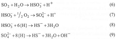
In the first step of a biological flue gas desulphurisation, sulphur dioxide is scrubbed from the flue gas using a biocarbonate solution (Equation 6). The presence of oxygen in the flue gas results in oxidation of part of the sulphite into sulphate (Equation 7). In the subsequent step, sulphite and sulphate are reduced under anaerobic conditions with an added electron donor {H} to sulphide by sulphate-reducing bacteria (Equation 8, Equation 9). In a micro-aerobic reactor, the sulphide produced is partially oxidized by autotrophic sulphur bacteria with concomitant production of hydroxide. Separation of the solid sulphur from the medium enables the recovery of elemental sulphur as a valuable product. The remaining alkaline solution, with a pH of about 9, can be re-used for the scrubbing of SO2. Because - along with SO2 - heat is also transferred from the flue gas to the scrubbing solution, it is economically attractive to operate the desulphurisation process at thermophilic conditions (50-65°C)23.
2.1.6 Magnesium enhanced lime (MEL) process
In the MEL process, slaked lime containing calcium hydroxide [Ca(OH)2] and a portion of magnesium hydroxide [Mg(OH)2], is used to react with SO2. The SO2, which is a strong acid gas, reacts with and is neutralized by the slaked lime. Calcium hydroxide in a slurry form, reacts with SO2 to form solid calcium sulphite (CaSO3.½H2O). Magnesium hydroxide reacts with the remainder of the SO2 to form soluble magnesium salts, magnesium sulphite and magnesium bisulphite [MgSO3, Mg(HSO3)2]. These soluble magnesium salts greatly increase SO2 capture and allow reduction in power consumption and equipment costs. When the magnesium sulphite is present in the slurry in contact with flue gas, it buffers (prevents from falling sharply) pH of the slurry as it absorbs acidic SO224. This improves absorber performance by increasing solubility of SO2 in the slurry, which allows operation at a lower liquid/gas (L/G) ratio. MEL is able to achieve high SO2 removal efficiencies in significantly smaller absorber towers than the limestone scrubbers. It also allows operation at a lower slurry pH, near 6.0, which improves reagent utilization to near 100 %25.
2.2 Semi-dry FGD processes
In this type of technology, the reactive reagent is introduced into the system as a fine suspension and results in a dry solid product.
2.2.1 Circulating fluidized bed (CFB) FGD process
Circulating fluid bed (CFB) and moving bed technologies, which utilize a dry sorbent to reduce SO2 emissions in a flue gas stream in a dedicated reaction chamber are categorized as dry scrubbers. The CFB principle for absorbing acid gases was developed in Germany in the 1970s26. In the mid-1980s, this process was used for flue gas desulphurisation in coal-fired power stations. Since 1984, only a few installations have been built in Germany and some neighbouring countries. Besides these plants, two North American units have been operational since 1995. There is also an operating CFB FGD plant at CINERGETIKA (Czech Republic). Handling a flow volume of 400 000 m3/h, it achieves a SO2 removal efficiency of 93 % at a Ca/S ratio of 1.4 and 70 % for Ca/S ratio of 1.327. In the circulating fluid bed (CFB) scrubber process, hydrated lime is injected directly into the CFB reactor. Water is also injected into the bed to obtain an operation close to the adiabatic saturation temperature. Flue gas enters the CFB reactor at the bottom, flows vertically upwards through a venturi section and enters the upper cylindrical vessel. The height of the bed is designed to accommodate the mass of bed material required to achieve a residence time of about 3 seconds. The process is easy to maintain and operate since it does not require high maintenance mechanical equipment such as abrasion resistant slurry pumps, water atomizers or sludge dewatering devices. The process can achieve > 95 % SO2 removal efficiencies. The CFB process, like any other dry post-furnace FGD process, has some generic advantages with respect to the widely used wet FGD technology: capital costs and energy consumption are low, installation is simple, construction time is short, little space is needed, and no wastewater treatment is required. However, the CFB process also shares some drawbacks with the other dry technologies: extremely high removal efficiencies are difficult to reach, the utilization of the expensive slaked lime is low to medium, the total amount of solid waste to be disposed of is great, and the risk of solid deposition inside the absorption unit is high, and, finally, the dust emissions from the ESP may increase due to the higher concentration of the particulate matter entering the collector26. The Tennessee Valley Authority has tested the gas suspension absorption (GSA) concept at a 10 MWe demonstration project28. Results of the test program indicated that the calcium/sulphur (Ca/S) molar ratio had the greatest effect on SO2 removal, with approach-to-saturation temperature next, followed closely by chloride content. At a Ca/S molar ratio of 1.4 with 18°F approach-to-saturation and 0.12 % chloride, the GSA/ESP achieved 90 % sulphur capture while the GSA/pulse jet baghouse (PJBH) achieved 96 % sulphur capture. In all the tests, a coal of sulphur content between 2.6 % and 3.5 % was used. On the operational, the GSA/ESP lime utilization averaged 66.1 % and GSA/PJBH averaged 70.5 %. The reactor achieved the same performance as a conventional spray dryer, but at one-quarter to one-third the size. Additionally, the GSA generated lower particle loading than a conventional spray dryer, special steels were not required in construction, and only a single spray nozzle is needed. High reliability and availability similar to other commercial applications were also demonstrated.
2.2.2 Spray-dry FGD process
The flue gas from the air heater is carried into the spray-dryer vessel, where it comes into contact with a finely atomized spray of lime and by-product slurry, delivered from a high-speed atomizer. This removes up to 95 % of the SO2 and most if not all SO3 and HCl17. The normal sorbent fed to this process is quicklime. This is slaked on site, with excess water, to produce a calcium hydroxide slurry (slaked lime). This is mixed with recycled by-product before being pumped to the rotary atomizer. Water is evaporated by the heat of the flue gas. The residence time (about 10 seconds) in the reactor is sufficient to allow for the SO2 and other acid gases, such as SO3 and HCl, to react simultaneously with the hydrated lime to form a dry mixture of calcium sulphate/sulphite. Waste water treatment is not required in spray dry scrubbers because the water is completely evaporated in the absorber. The flue gas, along with dried reaction products and solid particulate, is then passed through a fabric filter or an electrostatic precipitator. If a fabric filter is used, additional SO2 and acid gas removal occurs as the flue gas passes the built up filter cake on the bag.
As with other semi-dry systems producing a throw-away by-product, the spray-dry process is relatively cheap to install, typically being -70 % of the cost of the equivalent limestone gypsum system. However, the variable operating costs are among the highest of the major FGD processes, due to both the high lime usage and the costs of by-product disposal. Spray dry scrubbers are the second most widely used FGD technology. In commercial use, they have been known to achieve removal efficiency in excess of 90 % with some suppliers giving > 95 %. The total installed capacity worldwide is in excess of 15 000 MWe. The technology is well understood and offered by a number of contractors17,25.
2.3 Dry FGD processes
2.3.1 The duct sorbent injection process (DSI)
The in-duct desulphurisation process involves the injection of a dry sorbent, typically hydrated lime, in conjunction with flue gas humidification achieved by spraying water into the ductwork downstream from the air preheater but upstream from the particulate collection equipment. The main reaction binding the SO2 is a simple acid-base reaction:

The operating parameters of this DSI process are the Ca/S ratio and the approach to the adiabatic saturation temperature. Increasing the Ca/S ratio leads to higher SO2 removal yields but at the expense of lower sorbent utilization26. On the other hand, decreasing the approach to saturation temperature has a strong positive effect on the SO2 removal efficiency and sorbent utilization. However, there is a minimum practical approach to saturation of around 8-10°C due to the growing risk of solid deposits on the duct walls and on the internal parts of the process equipment and also due to corrosion of material. There are different DSI technologies based on three basic process alternatives - slurry injection and dry sorbent injection upstream/downstream from the spray humidification. The final product is a powdered mixture of calcium compounds. It is one of a number of FGD processes developed or being developed primarily for those instances in which a moderate degree of desulphurisation (50-75 %) is required on plant with limited operating hours and remaining lifetime17. So far, in-duct sorbent injection technology has been actively developed, mainly in the USA, since the 1980s. A 73.5 MWe demonstration was conducted in a US coal-fired boiler, achieving 50 % sulphur removal efficiency26 at flue gas temperatures of 149-154°C and Ca/S ratios 2-2.5. According to these data, sorbent utilization is less than 25 %. In this process, the lime was injected into the ductwork as a slurry.
2.3.2 Furnace sorbent injection
This is another process developed for moderate degrees of desulphurisation with low capital costs. The process involves the injection of hydrated lime into the furnace cavity of the boiler to absorb SO2. Spent sorbent is extracted with the fly ash in an ESP or fabric filter (FF). The final product is a mixture of fly ash and calcium compounds. There are very few plants now in commercial use, most being in Poland. It is one of the cheapest FGD processes to install but can be expensive to operate because it is inefficient in its use of sorbent. Because of this, sorbent injection is most suitable for retrofit situations. It is well suited to a situation where only low SO2 removal efficiency is required, and where there is little space available in the plant unit area12,15.
2.3.3 The sodium bicarbonate injection process
This process involves the direct injection of sodium bicarbonate into the flue gas duct downstream of the air heater, to react with and remove acidic compounds such as SO2, SO3 and HCl. The final product is a dry powdered mixture of sodium compounds and fly ash. It is suitable primarily for those applications where a moderate degree of desulphurisation is required at low capital cost, although it should be noted that the reagent itself is relatively expensive. Sodium bicarbonate is pneumatically injected into the fly ash as a fine dry powder. This removes up to ~70 % of the SO2 from the flue gas. From here, the gas is carried through the dust arrestor and the induced draft (ID) fan before discharge through the stack. All the particulate matter from the process is carried with the flue gas into the dust arrestor - an ESP or FF. Sodium scrubbing has been successfully employed at the Jim Bridger Power station in Wyoming29. The Electric Power Research Institute (EPRI) carried out the initial work on sodium scrubbing in 1978 and the Jim Bridger plant opened in the early 1980s. The Bridger plant is rated at 2200 MW (4 units). This installation clearly demonstrated the efficiency of sodium based FGD, however, the costs of the sodium absorbents for the system and waste stream management have prevented widespread use of sodium based scrubbing. There is ongoing research for the transformation of the sodium sulphate waste stream from the absorption step back into sodium bicarbonate sorbent and ammonium sulphate fertilizer. This would greatly improve the commercial viability of the process. The process can achieve SO2 removal efficiencies of up to 95 % and up to 98 % using dry sodium bicarbonate and a wet sodium carbonate solution, respectively. The extent of the NOx reduction is 40-95 % depending on conditions29.
2.3.4 Activated carbon
The activated carbon process is a regenerable process that adsorbs SO2 on a moving bed of granular activated carbon. After the adsorption, the activated carbon is thermally regenerated to produce a concentrated SO2 stream. SO2 may then be treated by conventional technologies to produce sulphuric acid25. The activated carbon adsorption process is known to have high adsorption capacities for diverse toxic gases because of the high surface area and microporous structure of activated carbon30. Advances in activated carbon FGD research have indicated that activated carbon fibres (ACF) have better performance characteristics than the carbon granules used in the early process31. Treatment with ammonia has been shown to enhance both the adsorption and oxidation capacity of ACF. However, beyond the laboratory scale, activated carbon FGD has not found widespread application in the industrial market31,32.
2.3.5 Copper oxide desulphurization
This is a regenerative process. The flue gas is brought in contact with CuO whereupon SO2 reacts with CuO and O2 to form copper sulphate in the temperature range 350-500°C. The sulphated adsorbent can then be regenerated with a reducing gas stream such as methane or carbon monoxide in the same temperature range used for sulphation. The concentration of SO2 in the regeneration off-gas is high enough for further processing to generate sulphuric acid or elemental sulphur33.
2.4 Combined SOx/NOx removal system
Both SO2 and oxides of nitrogen (NOx) are present in flue gases. Since emissions of both is regulated, it would, in principle, be highly desirable to remove both using the same process. However, despite the fact that both are acidic (and therefore amenable to reaction with a range of alkaline substances), in practice, separate methods are normally used for the control of each; conventional FGD processes are used to restrict SO2 emissions and NOx are limited either by combustion measures or selective catalytic reduction (SCR). One reason for this is that any combined SOx/NOx removal (SNOX) system would have to be sufficiently effective at removing both species that no further system is required. There are only a few plants operating worldwide that can remove both NOx and SO2 and those that are running are complex and expensive, although efficiencies over 90 % for both emissions can be achieved. Combined processes in operation include the activated carbon process, Wet-Gas Sulphuric Acid integrated with SNOX (WS A - SNOX) process, Degussa-SNOX (DESONOX) process29, and NOXSO. These types of plants are currently in operation in Denmark (1 retrofit), Germany (2 new, 7 retrofit), Italy (1 retrofit) and the USA (1 new, 9 retrofit).
Typical reactions for the SNOX processes are34:
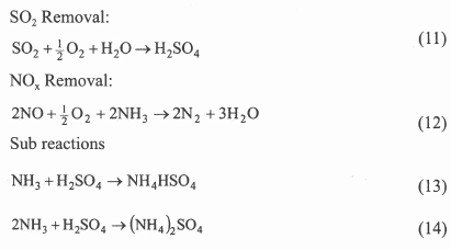
2.4.1 Electron beam ammonia (EBA) process
The electron beam flue gas treatment technology is one of the most advanced technologies among new generation processes for air pollution control. The process which has been developed in Japan, the United States, Germany and Poland allows simultaneous removal of SO2 and NOx. Over the last 20-25 years, research on the process has been done in many laboratories and pilot plants. The EBA process consists of three main stages: gas cooling, ammonium injection and electron beam irradiation, and by-product collection and treatment. After ash collection, the flue gas is passed through a spray cooler where it is cooled by water sprays. The cooled gas is then introduced into the process vessel and irradiated with electron beams after the injection of ammonia. The powder by-product is collected by the ESP and the treated clean gas is discharged into the atmosphere through the stack.
EBA reaction mechanism; The core of the EBA process is a "Process Vessel" where electron beam irradiation causes the main reactions to occur in three stages35. The first stage is the formation of active radicals such as OH, O and HO2. The second stage is the oxidation of SOx and NOx by free radicals to form sulphuric acid and nitric acid, respectively. The third stage is the neutralization of these acids by the injection of ammonia to form dry ammonium sulphate and ammonium nitrate solids. Three big pilot plants were installed in coal-fired electric power stations (EPS) at Indianapolis (USA), Nagoya (Japan) and Kawêczyn (Poland). The experience gained during their operation has allowed the preparation of full-scale industrial plant designs. The first such installation was built at EPS Chengdu (China). This is the first full scale EBA desulphurisation unit to operate in the world. Its designed flue gas treatment capacity is 300 000 Nm3/h. The plant demonstrated a SO2 removal efficiency of 80 % and a NOx removal efficiency of 10 %35,36. Another plant is located in EPS Pomorzany in Szczecin in Poland and treats a maximum of 270 000 Nm3/h of flue gas from two boilers. Removal efficiencies of up to 95 % for S02 and up to 70 % for NOx have been achieved in this plant37. In 2001, the Chubu Electric Power Company Inc. (Japan) put into operation another unit at its EPS Nishi-Nagoya for treating 620 000 Nm3/h of flue gas from a 220 MWe oil-fired boiler38. The energy consumption in this kind of technology has been estimated at 2-4 % of the total energy produced at the plant39.
2.5 Challenges facing future FGD technologies
There are three major challenges that face research and development in FGD systems namely to: reduce FGD costs, increase desulphurisation efficiencies, and improve system reliability. Currently, the FGD system increases the cost of electricity by about 10 %40. Greater in-depth knowledge can reveal the factors that control process performance, and lead to substantial enhancement of FGD processes. Basic research is needed in three broad categories : reaction mechanisms and sorbent material, transport effects and modelling, and process development.
More knowledge of the inherent kinetics and controlling resistances in all areas of the SO2 capture process is needed in order to improve the capture efficiency and reduce costs. For example, there is a need to elucidate the chemical mechanism(s) that allow successful sorbent additives to be effective. Recent researchers have shown that the use of organic and formic acids can improve the sorbent utilization and process efficiency in wet FGD applications16,18,41. The use of ammonium salts has also been shown to be beneficial to the limestone utilization and performance efficiency in wet FGD processes42,43. These additives act as buffers in the absorber and increase the limestone dissolution. Additional research will be necessary in order to make the use of additives commercially viable.
Poor sorbent utilization in the dry and semi-dry processes limits their economic feasibility. Sorbent preparation techniques used today have generally been adapted from those traditionally used in the lime industry. These preparation techniques need to be examined with an eye to the optimization of the properties important to the SO2 capture process. Further, little attention has been paid to the selection of limestone for the SO2 capture process44. Criteria must be established for limestone selection so that locally available limestone can be evaluated and used. The improved utilization of new sorbents such as calcium silicate sorbents formed from lime and fly ash has been demonstrated in laboratory scale FGD units45-48. Further research is needed on its viability in large scale industrial operations. In cases where low one-pass utilizations are inevitable, unreacted sorbent separation and recycle can serve to give high overall utilizations and reduce the volume of solid products. Davini50 showed that sorbents sulphated at high temperature can be partly regenerated by a suitable steam treatment. Innovative separation technologies such as membrane separation and electrochemical processes may lead to new process concepts applicable to FGD processes.
Opportunities exist to find methods of improving the efficiency of contacting operations between the flue gas and the sorbent, for example by using counter-current rather than co-current contacting. The use of smaller, more effective scrubbers is another area that is currently being pursued to reduce FGD capital and operating costs. One approach that is being evaluated is the design of systems that can operate at high flue gas velocities41,49. The higher flue gas velocity has the additional advantage of improving SO2 absorption rate as a result of increased turbulence, increased time that the slurry droplets remain suspended, and a decrease in the film thickness of the droplets.
3. Conclusions
FGD is the most widely used technology for the control of SO2 emissions from fossil-fired boilers. A wide variety of FGD technologies are available. The most commonly used are the limestone/gypsum (and its variations) and the spray-dry process, but newer technologies such as the CFB, sea water washing and the Electron Beam Ammonia (EBA) are rapidly gaining acceptance. Worldwide, there are currently 678 FGD systems operating on a total capacity of 229 GWe. A steady improvement in process design over the years means that modern designs can achieve more than 95 % sulphur removal efficiency. Costs have fallen steadily as the process became better understood and are now equivalent to $100-125 kW-1. Additionally, better knowledge of the process has made it possible to design units with high availability rates and thus eliminate the need for spare modules. Several new processes are under development, many of which are designed to remove both SOx and NOx. In recent years researchers have been investigating the design and operation of wet FGD modules with high gas velocities. This will help in making future FGDs smaller and more reliable.
References
1. Spalding-Fecher R, Matibe D, Electricity and externalities in South Africa, Energy Policy 31, 2003, 721-734. [ Links ]
2. Volcanic and Air Quality SO2 Service: Available from: http://www.oma.be/BIRA-IASB/Molecules/SO2archive/ [Accessed: 10/10/2007],
3. El-Wakil MM, Power Plant Technology, McGraw-Hill International Editions, 719-722, 1984.
4. Mitra AP, Sharma C, Indian aerosols-present status, In Chemosphere 49, 2002, 1175-1190.
5. National Environmental Management: Air Quality Act. South African Government Gazette, (27318), 476, February 24, 2005.
6. Chaaban FB, Mezher T, Ouwayjan M, Options for emissions reduction from power plants: an economic evaluation, Electrical Power and Energy Systems 2004, 26, 57-63. [ Links ]
7. Kaminski J, Technologies and costs of S02-emissions reduction for the energy sector, Applied Energy, 2003, 75 165-172. [ Links ]
8. Rubiera F, Moran A, Martinez O, Fuente E, Pis J, Influence of biological desulphurisation on coal combustion performance, Fuel Processing Technology, 1997, 52, 165-173. [ Links ]
9. Xie W, Liu K, Pan W-P, and Riley JT, Interactions between emissions of SO2 and HCl influidized bed combustors, Fuel, 1999, 78, 1425-1436. [ Links ]
10. Abadie LM, Chamorro JM, Valuing Flexibility: The case of an integrated gasification combined cycle power plant, Energy Economics, 2006, Article in press.
11. Nolan PS, Flue gas desulphurisation technologies for coal-fired power plants, Coal-Tech 2000 International Conference, November 13-14, 2000, Jarkata, Indonesia.
12. Golesworthy TA, Review of Industrial Gas Cleaning (3). Filtration and Separation, 1999, 36, 16-19. [ Links ]
13. Zheng Y, Kiil S, Johnsson JE, Zhong Q, Use of spray dry absorption product in wet flue gas desulphurisation plants: pilot scale experiments, Fuel 2002, 81, 1899-1905. [ Links ]
14. Kiil S, Nygaard H, Johnson JE, Simulation studies of the influence of HCl absorption on the performance of a wet flue gas desulphurisation pilot plant, Chemical Engineering Science, 2002, 57, 347-354. [ Links ]
15. Maller G and Hollinden J, Status of flue gas desulphurization (FGD) technology, Available online on 20/04/2007 at: http://apec-egcfe.fossil.energy.gov/7thtech/p112.pdf
16. Clean Coal Technology: Advanced Technologies for the control of Sulphur Dioxide Emissions from Coal-Fired Boilers, Technical Report (12), June 1999.
17. Technology Status Report 012: Flue gas desulphurisation technologies, Department of Trade and Industry, March 2000, CB013.
18. Frandsen JBW, Kiil S, Johnsson JE, Optimisation of a wet FGD pilot plant using fine limestone and organic acids, Chemical Engineering Science, 2001, 56, 3275-3287. [ Links ]
19. Skaninavisk Milj0 Service (SMS), Available online on 23/10/2007 at: http://www.sms.dk/seawater.htm
20. Balint SJ, Flue gas desulphurisation from Scottish perspective. Inst. Chem. Eng. Symp. Ser, 1995, 138, 85-95. [ Links ]
21. ComstockLK, Partnering enhances New Mexico power plant project, 6(1) communique April 1998.
22. Taylor HS and Nischt W, San Juan Generating Station FGD retrofit project update, Power-Gen International '98, December 9-11, 1998, Orlando, Florida, USA.
23. Goorissen H, Thermophilic methanol utilization by sulphate reducing bacteria, Thesis, Department of Microbiology of the University of Groningen, The Netherlands. [ Links ]
24. DePriest W and Gaikwad R, Economics of lime and limestone for control of sulphur dioxide, National Lime Association, Sargent and Lundy, 2002, Available online on 23/10/2007 at: http://www.lime.org/NLAdryFGD.pdf
25. Srivastava RK, Controlling S02 emissions: A review of Technologies, US EPA/600/R-00/093, November 2000.
26. Gutierrez Ortiz F J, Ollelo P, A pilot plant technical assessment of an advanced in-duct desulphurisation process. Journal of Hazardous Materials, 2001, B83, 197-218. [ Links ]
27. Desulphurisation Plant at Cinergetika (Czech Republic), Available online on 24/10/07 at: http://www.dipez.cz/english/osirovac.htm
28. Clean Coal Technology Demonstration Program, Environmental Control Devices, SO2 Control Technologies, 10-MWe Demonstration of Gas Suspension Absorption, Project Fact Sheets 2003.
29. Mortson M, Telesz RW, Flue gas desulphurisation using recycled sodium bicarbonate, The U.S. EPA/DOE/EPRI Combined Power Plant A ir Pollutant Control Symposium "The Mega Symposium" August 20 - 23, 2001.
30. Lee Y-W, Kim H-J, Park J-W, Choi B-U, Choi D-K, Park J-W, Adsorption and reaction behaviour for the simultaneous adsorption of NO-NO2 and SO2 on activated carbon impregnated with KOH, Carbon, 2003, 41, 1881-1888.
31. Boudon JP, Surface chemistry of a viscose-based activated carbon cloth modified by treatment with ammonia and steam, Carbon 2003, 41, 1955-1963. [ Links ]
32. Boudon JP, Chehimi M, Broniek E, Siemieniewska T, Bimer J, Adsorption of H2S or SO2 on an activated carbon cloth modified by ammonia treatment, Carbon, 2003, 41, 1999-2007. [ Links ]
33. Lin YS, Deng SG Removal of trace sulfur dioxide from gas stream by regenerative sorption process, Separation and Purification Technology, 1998, 13, 65-77. [ Links ]
34. Schoubye P, Enevoldsen S, Topsøe H and Ricci R, The SNOX process for power plants using high sulphur fuels, Sulphur International Conference, 2001, Marrakesh, Morocco, 28 October 2001.
35. Doi Y, Nakanishi I, Konno Y, Operational experience of electron beam purification of flue gas, Radiation Physics and Chemistry, 2000, 57, 495-499. [ Links ]
36. Yuqing Y, The status of FGD Technology and its prospects in coal-fired power plants in Sichuan Province - China, Available online on 10/4/2007 at: http://apec.egefefossil.energy.gov/7thTech/p90.pdf
37. Andrzej GC, Janusz L, Andrzej P, Bogdan T, Zimek Z, Operational experience of the industrial plant for electron beam flue gas treatment, Radiation Physics and Chemistry, 2004, 71, 442-444. [ Links ]
38. Licki J, Chmielewski AG, Iller E, Zimek Z, Mazurek J, Sobolewski L, Electron-beam flue gas treatment for multi-component air-pollution control, Applied Energy 2003, 75 145-154. [ Links ]
39. Radoiu M, Martin D, Georgescu II, Calinescu I, Bestea V, Indreias I, Matei C, A laboratory test unit for exhausted gas cleaning by electron beam and combined electron beam-micro-wave irradiation, Nuclear Instruments and Methods in Physics Research B 139, 1998, 506-510. [ Links ]
40. IEA Coal Research, Air pollution control costs for coal-fired power stations, The Clean Coal Centre, PF 01-12, December 2001.
41. Gohara WF, and Strock TW, New Perspective of wet scrubber fluid mechanics in an advanced tower design, EPRI-DOE-EPA Combined Utility Air Pollutant Control Symposium, August 25-29, 1997, Washington DC, USA.
42. Stergarsek A, Gerbec M, Kocjancic R and Frkal P, Modelling and experimental measurements of limestone dissolution under enhanced wet limestone FGD conditions, Acta Chim. Slov., 1999, 46, 323-338. [ Links ]
43. Takashina T, Honjo S, Ukawa N and Iwashita K, Effect of ammonium concentration on SO2 absorption in a wet limestone gypsum FGD process, The Society of Chemical Engineers, Japan, 2002, 35 197-204. [ Links ]
44. Kadambi JR, Prudich ME, Fan LS, Raghunathan K, Khang SJ, and Keener TC, Flue gas desulphurisation for acid rain control, Dry Scrubbing Technologies for Flue Gas Desulfurization, Editor: Barbara Toole-O'Neil, 1998.
45. Karatepe N, Ay seguí E-M, Ugur D and Kucukbayrak S, Determination of the reactivity of Ca(OH)2 - fly ash sorbents for SO2 removal from flue gases, Thermochemical Acta, 1998, 319, 171-176. [ Links ]
46. Lee KT, Bhatia S, Mohamed AR, and Chu KH, Optimizing the specific surface area of fly ash-based sorbents for flue gas desulfurization, Chemosphere, 2006, 62, 89-96.
47. Liu C-F, Shih S-M, and Lin R-B, Kinetics of the reaction of Ca(OH)2/fly ash sorbent with SO2 at low temperatures, Chemical Engineering Science, 2002, 57, 93 - 104. [ Links ]
48. Renedo MJ, and Fernandez J, Preparation, characterization, and calcium utilization of fly ash/Ca(OH)2 sorbents for dry desulfurization at low temperatures. Ind. Eng. Chem. Res., 2002, 41, 2412-2417. [ Links ]
49. Williams PJ, Wet flue gas desulfurization pilot plant testing of high velocity absorber modules, EPRI-DOE-EPA Combined Utility Air Pollutant Control Symposium, August 16-20, 1999, Atlanta, Georgia, USA.
50. Davini P, Properties and reactivity of reactivated calcium-based sorbents, Fuel, 2002, 81, 763-770. [ Links ]
Received 10 April 2007
Revised form 9 October
Accepted 25 January 2008
