


Services on Demand
Journal

Article
 English (pdf)
 Article in xml format
 Article references
 Send this article by e-mail
Indicators
Related links
-
 Cited by Google
 -
 Similars in Google
Share

 Permalink
R&D Journal
On-line version ISSN 2309-8988Print version ISSN 0257-9669
R&D j. (Matieland, Online) vol.30 Stellenbosch, Cape Town 2014
A Numerical Analysis of Machining Induced Residual Stresses of Grade 5 Titanium Alloy
R.F. LaubscherI; G. StyserII; G.A. OosthuizenIII
IDepartment of Mechanical Engineering Science, University of Johannesburg, South Africa, rflaubscher@uj.ac.za
IISAIMechE (Member), Department of Mechanical Engineering Science, University of Johannesburg, South Africa
IIIDepartment of Mechanical Engineering Science, University of Johannesburg, South Africa
ABSTRACT
Machining induced residual stresses may have a significant effect on the mechanical performance of machined parts. AdvantEdge is an advanced finite element code dedicated to the modelling of the machining process. This paper describes a comparative evaluation of modelling results obtained with AdvantEdge with experimental results obtained during turning of Grade 5 (Ti6Al4V) titanium alloy. A two dimensional orthogonal turning process is modelled and compared with experimental data. Comparisons are made relative to residual stress, cutting force and cutting temperature for various different cutting parameters including cutting speed, feed rate and cut depth.
Nomenclature
Roman
h chip thickness [mm]
G segmentation ratio
T temperature [C]
Greek
ε strain
σ stress [Pa]
Γ strain rate sensitivity ratio
Subscripts
f failure
i initial
m melt
r room temperature
0 reference
1 Introduction
In general most manufacturing techniques alter the surface integrity of the final component. Surface integrity refers to the surface properties and their influence on the functional performance of manufactured components1. Machining induced residual stress is a surface integrity descriptor that may have a significant influence on the mechanical behavior of metallic parts subjected to dynamic loads2. Most manufacturing processes introduce some form of residual stress to the material. Cutting or more specifically machining involves large plastic deformation and elevated temperatures that may induce significant residual stresses in the surface and near surface region. When turning steel these stresses are largely tensile in nature and extend to a depth of approximately 200 μm1.
Titanium alloys are important light metals that are becoming more mainstream with the current drive towards more energy efficient engineering and resource management. Grade 5 (Ti6Al4V) is the most popular titanium alloy currently in use because of its high specific strength when compared to other metals. Titanium alloys are specifically sensitive to the introduction of residual stresses during machining, especially during high speed machining, because of their high temperature toughness, high chemical reactivity and low thermal conductivity3. Chip segmentation also occurs readily even at lower speeds contrarily to most metals where segmentation is usually reserved for high cutting speeds. Various investigations have been conducted to establish the machinability of these alloys4,5.
The residual stress state of a machined surface is usually evaluated experimentally. This is difficult and expensive and usually involves a non-contact probing technique such as the x-ray diffraction technique (both high and/or low energy). Analysis and simulation of the cutting process may therefore significantly reduce the effort to quantify the residual stress state of a machined surface. Although numerical method codes that are dedicated to the simulation of the cutting process have appeared quite recently substantial effort has been ongoing into developing and expanding the current state of technology as regards to the simulation of machining of titanium alloys.
Obikawa and Usui6 presented a finite element investigation on the machining of Ti6Al4V. An effective strain-based criterion was used to model the serrated chip formation. Node failure or separation occurs when the effective plastic strain reaches some critical value that is a function of strain, strain rate, hydrostatic pressure and temperature.
Garud et al.7presented an investigation of improved titanium machining by modelling and analysis of 5-Axis tool paths during the machining of Ti6Al4V. They concluded that their semi-empirical model was able to accurately predict torque and cutting forces during drilling and milling operations of Ti6Al4V.
Hua and Shivpuri8 investigated chip morphology and segmentation during the machining of titanium alloys. They utilized an implicit Lagrangian based code, designed for metal forming operations, with crack initiation5 occurring by evaluating a critical damage value C that is obtained from a uniaxial tensile test. C is a function of temperature and microstructure. Once this critical value is reached the element is deleted and the rough boundary that is then produced smoothed by the addition of some "new points". A constitutive model that included strain rate sensitivity, temperature softening and microstructural changes was utilized. They concluded that the chip formation process is strongly influenced by crack initiation and propagation. Discontinuous chips are formed at low cutting speeds (1.2 m/min) and serrated chips at higher cutting speeds (120 m/min).
Calamaz et al.9 introduced a new material constitutive law to simulate the serrated chip formation during the 2D turning of Ti6Al4V. Their constitutive model is based on a modified version of the well know Johnson Cook law5. According to the Johnson Cook law the flow stress is given by:

Where σ is the equivalent flow stress, ε is the equivalent plastic strain, έ the equivalent strain rate, έ0 is a reference equivalent strain rate, T is the workpiece temperature, Tr is the room temperature and Tm is the melt temperature of the workpiece material. A, B, C and m are material parameters that are determined from high strain rate testing usually conducted with a Split Hopkinson pressure bar test. Calamaz et al.9 proposes a new model:
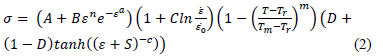
Where D= 1 -  , S =
, S =  and a, b, c and d are material constants. This model includes the hypothesis of dynamic recovery and recrystallization by including a term that allows for a constant flow stress beyond a certain strain. At low strains the flow stress increases because of strain hardening in a similar way as described by the Johnson Cook law. They concluded that this modification resulted in correct modelling of a serrated chip at low cutting speeds (60 m/min) and feeds (0.1 mm/rev) whereas the Johnson Cook model predicted a continuous chip for these cutting parameters. They further concluded that their modified model was able to more accurately predict the chip morphology parameters at higher cutting speeds (180 m/min).
Sima and Ozel3 used the Calamaz modified Johnson Cook formulation presented in eq. 2 to investigate the chip formation during orthogonal cutting of Ti6Al4V by parametric variation of the appropriate material constants. They conclude that the flow stress formulation greatly affects the chip formation process, cutting forces and temperatures. They managed to successfully model a serrated chip formation without a damage model and confirmed the importance of the flow stress strain softening approach of the Calamaz modified Johnson Cook model. Increased flow stress softening as a function of temperature and strain increases the degree of chip serration.
Limited experimental investigations have been conducted to determine the extent of machining induced residual stresses on Ti6Al4V. Cutting parameters vary widely in these investigations and includes both dry and cooled cutting and milling and turning operations. In general these investigations have all reported compressive residual stresses on the surface10,11,12,13,14. Some authors have however reported that the surface residual stress does become more tensile at higher cutting speeds12,13 and may even be fully tensile depending on the cutting parameters.
Recently Özel and Ulutan15 investigated the induced residual stresses in face turning (dry) of titanium (Ti6Al4V) with experimentation and numerical analysis. They conducted depth profiling tests by selectively removing layers by etching. They obtained peak compressive residual stresses of approximately 300 MPa on the surface in the transverse cutting direction. Smaller tensile stresses were obtained on the surface along the cutting direction. The residual stress field extended to a depth of approximately 80 μm. No significant change in residual stress was noticed between the two cutting speeds utilized (55 m/min and 90 m/min).
This paper compares simulation results of orthogonal machining with experimental data available in the literature with specific emphasis on residual stress. The commercially available finite element code AdvantEdge is utilized and its ability to model machining induced residual stresses in Grade 5 is evaluated.
2 Experimental Work
The experimental residual stress measurements used for comparative purposes are reported upon in detail in Madyira et al.13.
In essence 75 mm Grade 5 round bar was turned in a CNC lathe at different speeds (50-200 m/min) , feeds (0.1 -0.4 mm/rev) and depths of cut (0.2 5 and 1 .0 mm). SAND VIK CNMA 12 04 08 Η 1 Ρ (unc oated carbide) inserts were used throu hout. his implied a ne ative ra e an le of , relief an le of and a tool nose radius of 0.8 mm. A conventional emulsified mineral oil based flood cooling system was utilized. The three main cutting forces were measured by a Kistler dynamometer. Light microscopy was used to evaluate the chip morphology. The chip segmentation ratio and chip segmentation frequency was measured for different cutting speeds and feed rates. The chip segmentation frequency refers to the numbers of segments per mm chip length. The chip segmentation ratio is given by:

Where hmax is the maximum chip thickness and hmin is the minimum chip thickness. Gs = 1 implies a completely segmented or discontinuous chip. Gs = 0 implies a fully continuous chip without any segmentation occurring.
Depth probed residual stress measurements were obtained by the diffraction technique. Synchrotron diffraction was conducted at the energy dispersive diffraction beamline at the BESSY 11 Synchrotron storage ring in Berlin. 1t has the capacity to resolve residual stresses up to a depth of 100 μm for titanium13.
3 Finite Element Model
3.1 AdvantEdge
Thirdwave Systems 1nc, AdvantEdge (Version 2D 5.9-043) is a dedicated finite element based program with specific application to 2D and 3D machining. 1t is based on a dynamic explicit Lagrangian formulation16. The model is built by selecting the type of machining operation (e.g. turning, broaching, sawing or milling) and then defining the necessary process parameters. Since the main interest of the current work is orthogonal turning the required process parameters are feed rate, depth of cut, length of cut, cutting speed and initial temperature of the workpiece. Cutting tool geometry including tool tip radius, rake angle and relief angle may all be individually set. The material properties of the tool and the workpiece also need to be defined. AdvantEdge contains an extensive materials library for both workpiece and tool materials. Users materials may however be defined if needed. In general the code is relatively simple to use with most of the simulation engine controlling parameters automatically set and not under control of the user.
The modelling procedure is based on a coupled thermo-mechanical analysis. A staggered procedure is adopted for the purpose of coupling the thermal and mechanical equations. Geometrically identical meshes for the thermal and mechanical models are used. Mechanical and thermal computations are staggered assuming constant temperature during the mechanical step and constant heat generation during the thermal step. A mechanical step is taken first based on the current distribution of temperatures. The heat generated by plastic work and friction is also computed during this step. The heat thus computed is transferred to the thermal mesh and the temperatures are recomputed by recourse to the Forward-Euler algorithm. The resulting temperatures are transferred to the mechanical mesh and are incorporated into the thermal-softening model, which completes one time-stepping cycle.
A continuous adaptive remeshing scheme is used to overcome severely distorted elements on the cutting interface. Mesh smoothing algorithms are also utilized to control element distortion further16.
Residual stress is evaluated after a single cut by numerical removal of the chip and tool after completion of the prescribed cut. A procedure allowing for thermo-mechanical relaxation is then conducted. Vibrations are damped and heat is allowed to dissipate sufficiently for the workpiece to attain the original room temperature.
3.2 Orthogonal Model
A simple outside turning process was modelled as a 2D orthogonal model. The model is presented in figure 1. The rake angle, relief angle, cutting edge radius and tool nose radius were all chosen to coincide with those used by Madyira et al.13 for comparative purposes. Certain simplifications need to be made to model a conventional outside turning process with an orthogonal model. Because the undeformed chip thickness varies along the tool nose radius (see figure 2) the feed as used in the orthogonal model was reduced to an average value based on a constant undeformed chip width and constant cutting area (feed rate x depth of cut).
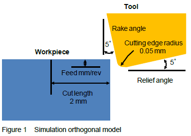
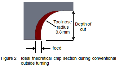
In this sense an equivalent feed and depth of cut was obtained for the orthogonal model based on the experimental feed, depth of cut and tool nose radius (see table 1).
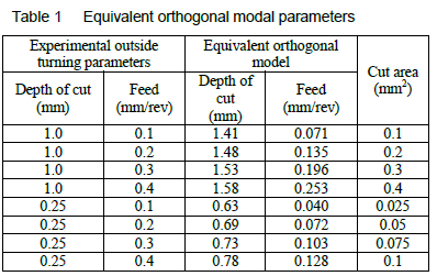
Two different cut depths (0.25 and 1.0 mm) and a range of different cutting speeds (70-200 m/min) are evaluated. Feed rates are varied between 0.1 and 0.4 mm/rev. Conventional flood cooling is modeled with an assumed overall heat transfer coefficient of 100 W/m2K. Vosough et al.17 did similar modelling and suggested values ranging from 29 - 300 W/m2K depending on the position, 300 W/m2K at the cutting interface and 29 W/m2K everywhere else. The sensitivity of the analysis to this parameter was briefly investigated by conducting a range of analysis at different overall heat transfer coefficients (101000 W/m2K). In general no significant difference in behavior was shown for the range of overall heat transfer coefficients evaluated.
A Coulomb frictional model is used to model the friction between the tool and rake face. A friction coefficient of 0.3 is assumed18.
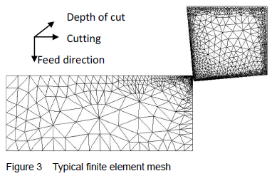
3.3 Meshing
AdvantEdge's adaptive continuous remeshing scheme was used. A maximum and minimum element size was specified as 0.1 mm and 0.01 mm. A maximum number of nodes of 72 000 was also specified producing a typical mesh as shown in figure 3.
3.4 Constitutive Modelling
AdvantEdge contains a number of so-c alled "validated" materials models for a large numbers of metals. These models cannot be modified by the user and needs to be used as is making it impossible to introduce unique "heat" or state properties of the specific alloy in question. First attempts to use the built-in Grade 5 constitutive model available in the software presented mixed results. Chip segmentation and cutting forces were adequately modelled, when compared to experimental data, but the residual stress field near surface was modelled as fully tensile when most literature data suggests it should be compressive for Grade 5. A dedicated constitutive model was therefore created that allowed incorporation of experimentally determined material properties along with literature sourced data.
3.4.1 Elastic Properties
Elastic properties as reported by Madyira et al. were used13. Elastic modulus, 115 GP a and Poisson's ratio 0.3.
3.4.2 Strain Hardening
A power law strain hardening function is utilized. This is given by:
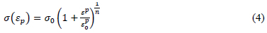
Appropriate material constants were derived from experimental uniaxial tensile tests. is the equivalent plastic strain,σ0 is the initial true yield stress, 968 MPa, is the reference plastic strain, 0.001 and n is the strain hardening exponent, 20. It is also further assumed that no further strain hardening occurs beyond a strain of 0.2 and the material thus behaves in a perfectly plastic behaviour beyond this strain.
3.4.3 Thermal Softening
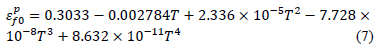
A polynomial thermal softening function is utilized with the data adapted from Seo et al.19:
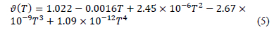
It is further assumed that the equation 5 is valid up to a 1000 °C beyond which the yield stress then reduces linearly to zero at a melt temperature of 1650⁰C.
3.4.4 Strain Rate Sensitivity
Machining may occur at strain rates up to approximately 105 s-1. Strain rate sensitivity is incorporated with the following function:
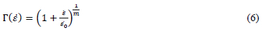
Where ε is strain rate, έ0 is a reference plastic strain rate 1 s-1 and m is the rate coefficient 50.5. Data was once again adapted from Seo et al.19.
3.4.5 Damage
Damage (D) is defined as the ratio of accumulated plastic strain versus the instantaneous strain to failure. It is evaluated incrementally and a region is deemed failed when D > 1.0. Its temperature dependenc e is incorporated by defining a polynomial curve fit of strain to failure versus temperature:
Curve fitting is based on data by Kim et al.20. n upper bound ut off temperature of 800⁰C was assumed where no further dama e is a umulated be ause of dynami recrystallization and recovery. This corresponds to a strain of appro imately at .
3.4.6 Thermal Properties
he thermal ondu tivity was varied linearly as a fun tion of temperature between 20⁰C (6.6 W/m°C) and 1050⁰C (21.5 W/m⁰C). The heat capacity was varied linearly as a function of temperature between 20⁰C (565 J/kg⁰C) and 980⁰C (1060 . n e pansion oeffi ient of -5 C-1 was used and a density of 4430 kg.m-3. All data from Calamaz et al.9.
4 Results
4.1 Chip Morphology
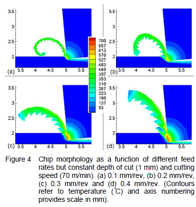
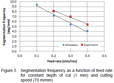
Temperature contour plots at a conventional cutting speed of 70 m/min and four different feed rates (0.1, 0.2, 0.3 and 0.4 mm/rev) are displayed in figure 4. The plots clearly show the presence of segmented chips throughout. Titanium alloys are known to display segmented chips even at low speeds and various investigations have been made to incorporate this into numerical simulations3,4,9,21. It is clear from figure 4 that chip segmentation frequency is a direct function of feed. A larger feed implies a smaller segmentation frequency. A comparison between the experimentally measured and simulation segmentation frequency is presented in figure 5. The simulation gives an acceptable representation of the segmentation ratio if one takes into account the orthogonal assumption of the simulation which is clearly not the case for the experimental work. This provides some validation for the model. The results are also similar to those obtained by Sima and Özel3 in that they also showed that the segmentation frequency is a strong function of the feed rate.
4.1 Cutting force
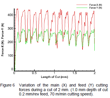
The variation of the main and feed cutting forces during a typical cut is presented in figure 6. The effect of the chip segmentation is clearly visible in the variation of the force. The cutting occurs in two basic steps. The first step is an upsetting phase where the workpiece is compressed before the cutting force rises dramatically until it reaches the second stage where an adiabatic shear zone is activated where segmentation then occurs accompanied by a rapid drop in force.
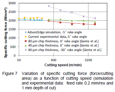
The variation of the resultant specific cutting force (resultant cutting force/cut area) as a function of cutting speed is presented in figure 7. In general the simulation provides a good approximation of the cutting force when compared to the experimental data13. It also compares favourably with the high speed cutting data of Gente et al.2 albeit extrapolated to lower speed and a slightly different rake angle. The data clearly shows that the specific cutting force does not vary appreciably with cutting speed at low rake angles but does decrease slightly because of thermal softening effects at the higher cutting speeds.
4.2 Cutting Temperature
Contour plots depicting the variation of temperature as a function of feed rate are presented in figure 4. It is clear from these that higher temperatures are generated at higher feed rates. The variation of the maximum cutting temperature as a function of feed rate is presented in figure 8.
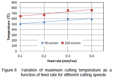
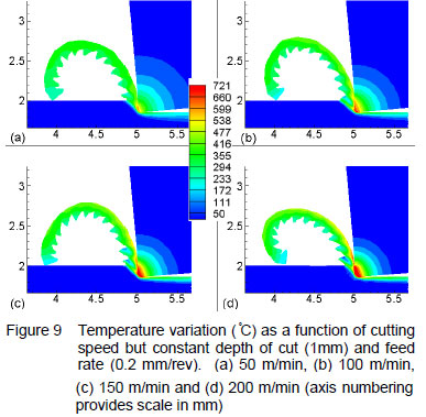
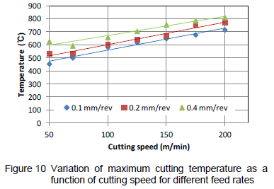
Figure 9 presents temperature contour plots for a constant feed rate as a function of cutting speed. This once again clearly shows that increased cutting speed implies an increased heat load leading to higher overall cutting temperatures. The figure also suggest that the chip curling is a function of the temperature gradient between the inner and outer chip surface temperature which implies that invariably it may also vary with cutting speed. The variation of maximum cutting temperature as a function of cutting speed, for different feeds, is presented in figure 10. This shows that the maximum cutting temperature will increase by up to 250 °C if the cutting speed is increased from the conventional speeds (50-70 m/min) to the highest practical speeds (150-200 m/min) where rapid tool deterioration is known to occur when machining Grade 5.
The data clearly shows that higher cutting speeds and feed rates leads to higher cutting temperature. In the case of the higher feed rate more heat is produced because of the larger volume of material that is being deformed and cut. In the case of the higher cutting speed the heat generation rate is increased leading to a rapid rise in temperature in the cutting zone. This is largely the result of the relatively low heat conductivity properties of titanium alloys.
4.3 Residual stress
Contour plots displaying longitudinal residual stress as a function of feed rate and cutting speed are presented in figures 11 and 12. The residual stress field is mostly compressive at and near the surface before becoming tensile in the interior to then eventually attaining the unstressed parent material stress field. This is markedly different from steel which mostly displays a tensile stress field near surface. The low thermal conductivity of titanium and its alloys is largely responsible for this behaviour. The heat generated by friction and plastic deformation during the machining process requires more time to dissipate by conduction into the workpiece and quenching on the surface. This leads to a near subsurface region that cools down (and therefore contracts) more slowly than the surface and therefore eventually places the surface in compression as it attains the equilibrium temperature.
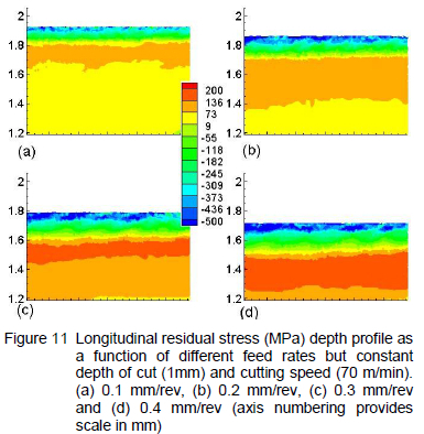
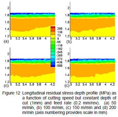
Figure 11 clearly shows that feed rate has a marked effect on the residual stress depth profile. Higher feed rates imply an extended (deeper) residual stress field and higher absolute stress values. This is caused by the higher thermal load that the higher feed rate and therefore more pronounced plastic deformation implies. This effectively exacerbates the thermal effect alluded to above.
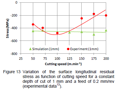
Figure 12 presents longitudinal residual stress contour plots as a function of cutting speed for constant feed rate and depth of cut. These show that the residual stress profile should be largely independent of cutting speed. Literature data13 however shows otherwise. Figure 13 presents plots comparing experimental data with the simulation results for the surface residual stress as a function of cutting speed. Although the absolute values are comparable at the lower (conventional) cutting speeds the experimental literature12,13 clearly shows that the residual stress should become more tensile with increasing cutting speed above a certain critical value. It is believed that this threshold is a function of the heat balance in the cutting region. Above this threshold increasing speeds lead to increasing thermal load but also less time for conduction to occur. The largely tensile plastic deformation component then seems to become dominant. The current model does not adequately capture this behaviour. It assumes a constant overall heat transfer coefficient and constant friction coefficient that may be an over simplification as far as the thermal aspects of the modelling is concerned. More detailed modelling with a more general purpose non linear finite element code will be required to investigate this further.
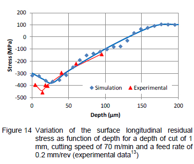
The variation of longitudinal residual stress as a function of depth for a conventional cutting speed of 70 m/min and depth of cut of 0.2 mm/rev is presented in figure 14. Good agreement between the experimental work and the simulation is realized. The simulation correctly captures the fact that the maximum compressive residual stress is actually located at a finite distance inboard of the surface. This point is located at approximately 25 μm for the simulation compared to the 14 μm of Madyira et al. 13
5 Conclusion
This paper presents a numerical simulation of outside turning of Grade 5 titanium alloy. The simulation results are compared and validated with experimental work. A dedicated constitutive material model had to be used to correctly capture the observed experimental behavior. This constitutive model is based on actual experimental work conducted and published data for Grade 5. Reasonable agreement between published data, experimental work and the simulation results as far as cutting forces and chip morphology is achieved. The simulation presents a good approximation of the residual stress field at conventional cutting speeds. It correctly presents a fully compressive residual stress field. The simulation correctly captures the fact that the maximum compressive residual stress is actually located a finite distance below the surface. It does however not accurately capture the cutting speed sensitivity as observed in the literature. This is believed to be related to the thermal modelling component of the simulation that assumes a simple Coulomb friction model and a constant overall heat transfer coefficient along with an assumed heat transfer over the tool workpiece interface. A more general purpose non linear finite element code where the user has more control of the thermal aspects (heat generation and dissipation) of the modelling will be required to investigate this further.
References
1. Davim JP Ed., Surface Integrity in Machining, 1st ed., Springer-Verlag, 2010.
2. Gente A and Hoffmeister H-W, Chip Formation in Machining Ti6Al4V at Extremely High Cutting Speeds, CIRP Annals, 50, 1, 49-52, 2001. [ Links ]
3. Sima M and Ozel T, Modified Material Constitutive Models for Serrated Chip Formation Simulations and Experimental Validation in Machining of Titanium Alloy Ti-6Al-4V, International Journal of Machine Tools & Manufacture, 50, 943-960, 2010. [ Links ]
4. Arrazola PJ, Garay A, Iriarte LM, Armendia M, Marya S and Le Maitre F, Machinability of Titanium Alloys (Ti6Al4V and Ti555.3), Journal of Materials Processing Technology, 209, 5, 2223-2230, 2009. [ Links ]
5. Johnson GR and Cook WH, A Constitutive Model and Data for Metals Subjected to Large Strains, High Strain Rates and High Temperatures, 7th International Symposium on Ballistics, 21, 541-547, The Hague, 1983.
6. Obikawa T and Usui E, Computational Machining of Titanium Alloy- Finite Element Modelling and a Few Results," Journal of Manufactuting Science and Engineering, 118, 208-215, 1996. [ Links ]
7. Garud S, Marusich T, Usui S, Zamorano L and Marusich K, Improved Titanium Machining: Modeling and Analysis of 5-Axis Tool Paths via Physics-Based Methods, SAE Technical Paper, No. 2009-01-3131, 2009.
8. Hua J and Shivpuri R, Prediction of Chip Morphology and Segmentation During the Machining of Titanium Alloys, Journal of Materials Processing Technology, 150, 124-133, 2004. [ Links ]
9. Calamaz M, Coupard D and Girot F, A New Material Model for 2D Numerical Simulation of Serrated Chip Formation when Machining Titanium Alloy Ti-6Al-4V, International Journal of machine Tools and Manufacture, 48, 275-288, 2008. [ Links ]
10. Rao B, Dandekar CR and Shin YC, An Experimental and Numerical Study on the Face Milling of Ti-6Al-4V Alloy: Tool Performance and Surface Integrity, Journal of Materials Processing Technology, 211, 294304, 2011. [ Links ]
11. Vasough M, Liu P and Svenningsson I, Depth Profile of Titanium (Ti-6Al4V) Alloy and Residual Stress Measured by Using X-ray Diffraction after Metal Cutting Assisted by High Pressure Jet Cooling Evaluation of Etching Methods: ION Beam (EDOS) and Electro-chemical Etching, Materials Science Forum, 490, 545-551, 2005. [ Links ]
12. Valasquez JD, Tidu A, Bolle B, Chevrier P and Fundenberger JJ, Sub-surface and Surface Analysis of High Speed Machined Ti-6Al-4V Alloy, Materials Science and Engineering A, 527, 10, 2572-2578, 2010. [ Links ]
13. Madyira D, Laubscher RF, Janse van Rensburg N and Henning P, High Speed Machining Induced Residual Stresses in Grade 5 Titanium Alloy, Proceedings of the Institution of Mechanical Engineers, Part L: Journal of Materials Design and Applications, 227, 3, 208-215, 2013. [ Links ]
14. Sun J and Guo YB, A Comprehensive Experimental Study on Surface Integrity by End Milling Ti6Al4V, Journal of Materials Processing Technology, 209, 4036-4042, 2009. [ Links ]
15. Ozel T and Ulutan D, Prediction of Machining Induced Residual Stresses in Turning of Titanium and Nickel Based Alloys with Experiments and Finite Simulations, CIRP Annals - Manufacturing Technology, 61, 547550, 2012. [ Links ]
16. Marusich TD and Ortiz M, Modelling and Simulation of High-Speed Machining, International Journal of Numerical Methods in Engineering, 38, 3675-3694, 1995. [ Links ]
17. Vosough M, Kalhori V and Svenninsson I, Influence of High Pressure Water-Jet Assisted Turning on Surface Residual Stresses on Ti-6Al-4V Alloy by Measurement and Finite Element Simulation, 3rd International Surface Engineering Congress, Orlando, Florida, 2004.
18. Hong Y, Ding Y and Jeong W, Friction and Cutting Forces in Cryogenic Machining of Ti-6Al-4V, Journal of Machine Tools & Manufacture, 4, 2271-2285, 2001. [ Links ]
19. Seo S, Min O and Yang H, Constitutive Equation for Ti6Al4V at High Temperatures Measured Using the SHPB Technique, International Journal of Impact Engineering, 31, 735-754, 2005. [ Links ]
20. Kim SW, Kim JH, Song YH, Hyun YT and Yeom JT, Deformation Characteristics of Ti-6Al-4Fe Alloys with Enhanced High Temperature Ductility, Materials Science & Engineering A, 559, 96-100, 2013. [ Links ]
21. Arrazola PJ and Ozel T, Investigations on the Effects of Friction Modelling in Finite Element Simulation of Machining," International Journal of Mechanical Sciences, 52, 31-42, 2010. [ Links ]
22. Ginting A and Nouari M, Surface Integrity of Dry Machined Titanium Alloys, International Journal of Machine Tools and Manufacture, 49, 325-332, 2009. [ Links ]
Received 1 August 2013
Revised form 26 June 2014
Accepted 30 June 2014
