


Services on Demand
Journal

Article
 English (pdf)
 Article in xml format
 Article references
 Send this article by e-mail
Indicators
Related links
-
 Cited by Google
 -
 Similars in Google
Share

 Permalink
R&D Journal
On-line version ISSN 2309-8988Print version ISSN 0257-9669
R&D j. (Matieland, Online) vol.12 Stellenbosch, Cape Town 1996
Residual stress evaluation using the air abrasive hole drilling technique
A.M. SegalI; R.B. TaitII
IStructural Engineer, Transwerk Ltd, P.O. Box 81055, Doornpoort, 0017 South Africa
IIAssociate Professor, Department of Mechanical Engineering, University of Cape Town, Private Bag, Rondebosch, 7700 South Africa
ABSTRACT
This paper describes the design and construction of an air abrasive centre hole (AACH) drilling facility and its application for measuring residual stress in extruded aluminium rods as a function of processing route. The AACH system facilitated normal (rectangular sided) small hole drilling with precise optical location. Calibration tests indicated errors of typically 5%. For the extruded aluminium rods examined significant tensile hoop stresses were measured on the outer surface of rods which were roll straightened; whereas for rods subjected to a 'stretch' straightening process, the outer surface residual stresses were much smaller, compressive and randomly oriented. Stress gradients measured through the thickness of the rods showed stress reversal, with the magnitude of the stresses on the inner surface lower than those on the outer surface. A simple ring splitting process yielded comparable but less accurate average residual stress results. From this investigation, it was apparent that although the 'stretch' route resulted in improved (i.e. reduced) residual stresses, the conventional processing route was quite acceptable.
Introduction and background
Residual stress is the term applied to a stress system which is locked into an article during its manufacture, and which does not disappear during the natural relaxation of the article when all external load constraints are removed.1 Although such residual stresses frequently tend to exist unnoticed, they are as real as any stress arising from applied loads or service conditions. Residual stresses are very common and can arise from various sources, such as transient temperature gradients, nonuniform plastic deformation, or property changes arising from fabrication or heat treatment operations.
Nomenclature
AACH air abrasive centre hole
1/K1 sensitivity constant in the residual stress equation
αdirection of first principal stress from the first strain gauge
εastrain measured by the first strain gauge element
εbstrain measured by the second strain gauge element
εcstrain measured by the third strain gauge element
εaaxial strain
ε'Arelaxed axial strain
εTrelaxed transverse strain
σ1first principal stress
σ2 second principal stress
vK2/K1constant in the residual stress equation
They can arise from virtually every forming and fabrication process, for example: casting,2 rolling,2,3 forming,2 stamping,2 drawing,1 extrusion,2 machining,2 or welding.2,4 These locked in stresses consist of a configuration of tensile and compressive stresses which are necessarily in equilibrium (including thermal equilibrium), and are independent of any applied loads or stresses.
Although the presence of residual stress in components and structures has long been recognised,2,5,6 it is only in the past few decades that emphasis has been placed on their significant effect on service performance. For example the sensitivity to stress-corrosion,7 fatigue behaviour,7-9 and measured fracture toughness10 can all be influenced by the magnitude and direction of residual stresses and hence they can have a significant impact on structural integrity, safety and reliability. Once present in a product, or component, residual stress can only be removed, and then usually only partially, by special forms of post-processing, such as stretching,3,11 vibration,11,12 annealing,2,3 or various forms of heat treatment,11 such as post weld heat treatment (PWHT). When the presence of residual stress is ignored, or when stress-relief is not feasible, the residual stress ordinarily remains in the product or component, except for some possible shakedown in service, and may subsequently interact with the applied stresses.
Residual stresses do not necessarily have an adverse effect on a component. They may be considered to have either favourable or unfavourable effects as seen from the engineering point of view depending on the circumstances. They are generally harmful if they act in the same direction as the critical applied stress, and beneficial if acting in the opposite direction to the local applied stress. Examples of the adverse and beneficial effects of residual stresses are not hard to find, and include, respectively, butt welded steel4 and carburised gears and gear teeth.3
Despite the widespread occurrence of residual stress and its importance for affecting component service performance and structural reliability, the subject is generally not well taught at many engineering universities. In addition, perhaps as a consequence, the quantitative evaluation and measurement of residual stress, and its treatment in design, lags behind the generally more well known stress analysis topics. There is therefore an urgent need for techniques for the reliable and ideally easy and non-destructive measurement of residual stress in components, as it is generally very difficult to calculate residual stress by analytical and computational methods, frequently because of unclear boundary conditions.
There are, however, various experimental techniques of residual stress measurement, each having their various attributes and their own characteristic advantages and disadvantages. These include the following:
• Diffraction techniques
X-ray diffraction13,14
Neutron diffraction15,16
• Stress sensitive techniques
Magnetic techniques17,18
Ultrasonic techniques4,19
Hardness techniques4
• Cracking techniques
Hydrogen induced cracking4
Stress corrosion cracking4
• Stress relaxation techniques
The brittle coating technique4,20
Sach's boring out technique1,3,4,21
The successive milling technique4
The trepanning or ring core technique22,23
Ring splitting and tongue techniques1,3,21
Deep hole drilling24
Crack compliance techniques25
• The centre hole drilling techniques, which include:
Low speed end mill drilling26-29
High speed drilling26,28 29
Air abrasive drilling26,29,30
In the present paper, the air abrasive centre hole (AACH) drilling technique was chosen due to its many advantages. Negligible machining stresses are induced during the drilling process due to the low-inertia of the tiny abrasive particles as well as the beneficial cooling effect of the air jet dissipating any heat build up.26,30 This is in contrast to other means of drilling - low speed end mill and high speed air turbine, which can result in significant hole induced stresses, particularly in tough materials such as stainless steels which have high strain hardening rates. The AACH technique is also a proven, reliable and accurate technique,26 which may be regarded as virtually non-destructive since only a small blind hole, of approximately 1.5 - 2 mm diameter and depth is produced.26,31 The equipment required is relatively inexpensive and the technique is portable.26 The availability of such units is limited, however, and in the present case a custom built in-house AACH system was designed and built, based on the design of Beaney and Procter.26,31
This paper describes the theory of the AACH drilling technique, the design and calibration of the required equipment, and the application of the technique in the measurement of residual stresses in high strength extruded aluminium (7075-T6) rods.
The air abrasive centre hole technique
Principles and analysis of the centre hole drilling technique
If a blind hole is drilled in an infinite or semi-infinite plane sheet of elastic isotropic material, which is subjected to a state of uniaxial stress, the radial stress at the edge of the hole must necessarily reduce to zero.32 A redistribution of the stress will occur in the vicinity of the hole, since the hole itself can carry no stresses. The radial stress in the vicinity of the hole is shown schematically in Figure 1.32
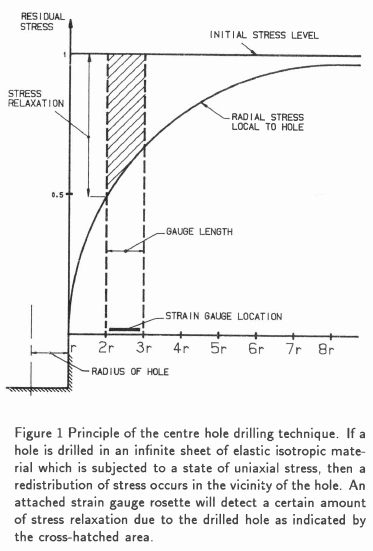
If a strain gauge were to be attached to the sheet before drilling, over a distance of 0.5d to 1.5d from the edge of the hole, where d is the diameter, then as the hole is drilled the strain gauge will detect the strain associated with the reduction in stress shown by the cross-hatching in Figure 1. This is related to the relaxation in stress at the edge of the hole. The relaxed strains measured by the strain gauges on the surface of the component are dependent upon the hole depth up to a certain point, beyond which further drilling does not significantly affect the strain. Schajer,33 Bathgate,34 Kelsey,35 and Rendler and Vigness27 have shown that the maximum strain has been released when the hole depth is equal to the hole diameter. Commercial suppliers, Micro-Measurements,36 and Standards' recommendations37 specify that the hole depth should equal 1.2 times the hole diameter to ensure that the optimum stress has been relieved from the hole.
In practice, rather than a single strain gauge being located close to where the hole is to be drilled, a three element strain gauge rosette is employed (typically 0°, 45°, and 90°) with the hole drilled at the common focus of the gauges. The conventional mathematical analysis31,32 allows only for cylindrical holes which have side walls normal to the surface of the specimen. Partial relaxation due to the drilled hole is measured, which is limited. Therefore hole diameters should be sufficiently large to relieve the maximum amount of strain possible, with the limitation that too large a hole could affect the strain gauge rosette due to machining effects. In addition, the technique should be nominally non-destructive, as too large a hole could lead to degradation of the structural integrity of the component. As a result, strain gauge manufacturers usually specify a range of hole sizes to be used with their specific strain gauge rosettes.
In an attempt to increase sensitivity of the stress relaxation technique from hole drilling, Schajer38 has recently proposed a hole drilling method whereby an inverse taper hole is drilled using a specially shaped high speed drill bit. This type of hole has the advantage of allowing more strain relaxation, thus increasing the sensitivity of the conventional hole drilling technique.
Regarding the application of the air abrasive centre hole drilling method, it is important for the hole to be 'drilled' centrally and symmetrically with respect to the three element strain gauge rosette. In addition, such hole 'drilling' needs to be undertaken in such a manner which results in a cylindrical hole whose side walls are normal to the surface of the specimen. This is achievable using a fine jet of small (typically 50 μmalumina) abrasive particles in a tilted and orbiting fashion, as described later.
The analysis by which relaxed strains, as measured from the surface mounted strain gauges, can be used to infer the original residual stresses, depends on the assumptions made about the residual stress fields. In particular there could be either a uniform "stress distribution or a stress distribution varying with depth. Frequently the former uniform stress case is assumed because the hole is small compared to the component size and the stress distribution can be assumed to be approximately uniform over this small depth. If it is known, however, that severe stress gradients are present, a more in-depth analysis is required, which is discussed shortly. For most cases, however, the uniform stress distribution is widely used and is presented here.
Uniform Residual Stress Distribution
The equations used for determining the principal residual stresses and their directions when a uniform residual stress distribution is assumed are derived by subtracting the biaxial stress solution for a thin plate from Kirsch's solution39 for a thin plate with a hole in it.40
After some manipulation, the equations reduce to the following:
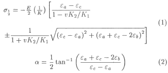
where σ1 = first principal stress; σ2 = second principal stress; εa = strain measured by the first strain gauge element; εa = strain measured by the second strain gauge element; εc = strain measured by the third strain gauge element; α = angle of σ1from the first strain gauge element; 1/K1 = calibration constant; and vK2/K1 = calibration constant.
As regards notation, if α is positive as determined from the strain input data, then it is measured in the direction of the strain gauge rosette i.e. clockwise from strain gauge 1.
Conversely, if a is negative, then it is measured in the counter direction of the rosette from strain gauge 1.
Equation (2) has two solutions in the range of -90 < α< 90 which can lead to confusion, as reported by Gupta41 and Wang.42 These two a solutions correspond with the direction of the two principal stresses. To determine the direction of σ1, the signs of the numerator (εa+ εc - 2εb) and the denominator (εc - εa)are ascertained, and the appropriate value of αis selected from reference to rules or tables.31
Certain researchers7,41,42 prefer to use other equation constants in equations (1) and (2). Instead of 1/K1and vK2/K1, they use A and B, but the equations are effectively similar. Constants A and B are dependent on material constants E (Young's modulus) and v (Poisson's ratio), whereas 1/K1and vK2/K1can be regarded as independent of these material constants,26,2,)40 since although still a function of v, the dependence is very weak.40 Schajer40 has reported that finite element calculations have shown, that for a hole of depth equal to diameter, K varies within a 2% range and vK2/K1varies from 0.27 to 0.32 for a range of v from 0.25 to 0.35. If a uniaxial stress field is assumed, then 1/K1and vK2/K1conveniently reduce to the following:26
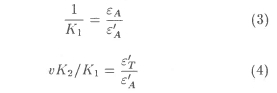
where εa - applied axial strain; ε'a =relaxed axial strain; and ε'T - relaxed transverse strain.
Beaney,26 and Beaney and Procter32 have shown that vK2/K1can be approximated as 0.3 or 0.33 and that 1/K1is a function of hole diameter, for a given strain gauge rosette. These constants can be found elsewhere.26,31
Thus when using the constants 1/K1and vK2/K1only one calibration is required for all elastic isotropic materials for a given hole diameter. In fact, one need only look at the constants given by researchers such as Beaney26,31 in order to determine these constants for a range of hole diameters. Finally, in the event of holes drilled not absolutely centrally, their eccentricity can be taken into account43 but the analysis is more complex, and the effect small if the eccentricity is not excessive (i.e. eccentricity less than about 4% of hole diameter).
Stress gradients varying with depth
Various attempts have been made to determine residual stress variation with depth,6'7,33-35,40,44-51 which have been less or more successful. These include the incremental strain method, the average stress method, the power series method and the integral method. These various methods attempt to calculate the residual stress gradient, within the hole from incremental strain data. It has been shown33,46 that the incremental strain method and the average stress method are generally somewhat inaccurate.
The power series method, developed by Schajer,40 makes use of finite element calculations to compute series of coefficients used to calculate residual stresses. It is particularly useful when analysing smoothly varying residual stress fields and many hole depth increments are made.
The integral method has been made practical by the use of finite element calculations as a calibration procedure. Initial developments of this method were made by Bijak-Zochowski,51 Niku-Lari et al.7and Flaman and Manning,46 which were further developed by Schajer.33,50 Although the procedure developed by Flaman and Manning was mathematically equivalent to Schajers solution, the latter's formulation is easier to use. The integral method considers the contributions to the total measured strain relaxation by the stresses at all depths simultaneously,33,46 and is a viable and practical procedure for calculating stresses varying with depth.50 It is best suited to the case where residual stresses vary sharply and where only a few hole depth increments are made.
As a final comment on non uniform stress distributions, Kabiri52 suggested that since there is no means of determining how the stresses vary near the hole, except by drilling another hole; a new 5-element strain-gauge rosette should be manufactured and employed. His reasoning was that a linear stress field, as opposed to a uniform stress field, could then be assumed and analysed. The analysis presented by Kabiri is a complex and lengthy one. Furthermore, residual stresses are complex, so more than one reading would be needed anyway.
Shaw and Chen48 proposed a method of measuring stresses varying in all directions. However they also suggested that in order to obtain the residual stress distribution over the whole specimen, several strain gauge rosettes should be attached to the specimen at appropriate positions. Lu and Flavenot45 suggested that chains of strain gauges could be used to measure the stress gradients in a plane. This configuration could also avoid plasticity effects due to the stress concentrations caused at drilled holes in large stress fields, but this approach is expensive in strain gauges.
It is felt that by using the standard 3-element strain gauge rosette intelligently and by having a good understanding for the problem at hand, it would not be necessary to use special 5-element or chain strain gauge rosettes, and such exotic rosettes have not achieved any great popularity. The use of conventional rosettes, together with the design of the air abrasive facility, is described in the next section.
Design, construction, and calibration of the AACH drilling equipment
The main points pertaining to the design and calibration of the AACH drilling equipment are discussed in this section; further details can be obtained elsewhere.53
The principle of the design of the AACH drilling equipment was similar to a unit designed by Beaney and Procter.26,31 The present facility resulted in an inexpensive working system, with essentially locally manufactured components.
Design requirements
In order to perform accurate residual stress measurements, the design requirements of the AACH drilling equipment were to provide the following capabilities:
1. Accurate positioning to within 20 μm of the combined strain gauged specimen / drill facility system, so that a hole could be drilled in the centre of the attached strain gauge rosette.
2. The ability to position the hole drilling device the required distance of 1.5 mm31 above the specimen.
3. Accurate drilling of the required hole size and geometry.
4. Accurate measurement of the hole diameter and depth, as well as any eccentricity or hole taper.
5. The extraction of swarf, debris, and alumina particles from the work area.
6. Supply an air-alumina stream at the operational pressure (5.5 bar, in this case).
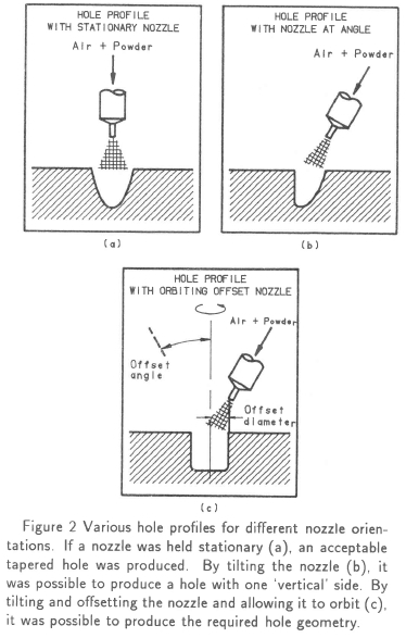
The most important of these requirements was the hole drilling operation. As mentioned previously, drilled holes were required to have sides at right angles to the surface, or so called 'vertical' sides (if the workpiece was horizontal). Such normal holes facilitate the use of the conventional mathematical derivations26,31 as opposed to inverted tapered hole derivations.38 To enable these holes to be drilled accurately, standard 0.46 mm sapphire nozzles were used which could be replaced when worn by the abrasive powder. For best results and low nozzle wear, the ideal nozzle to work surface distance was 1.5 mm.31
Were a hole to be drilled with the nozzle held stationary and perpendicular to the work surface, then a roughly rounded yet tapered hole, with the section approximately as shown in Figure 2(a) would result. Since such a hole has non-vertical sides, it is far from ideal. However if the nozzle were to be slightly tilted, a hole with one vertical side could be produced as shown in Figure 2(b). In addition, if the nozzle were to be given a certain offset and orbited, a vertically sided hole of chosen diameter could be 'drilled'. This concept is illustrated in Figure 2(c).
In order to fulfil the above requirements, an optical unit compatible with a drilling unit was proposed. The extent of their compatibility was that they would both be capable of being secured in a common guide bush. A test specimen could thus be accurately positioned beneath the guide bush with the aid of the optical unit and thereafter a hole drilled in the desired position with minimum deviation by replacing the optical unit, in the guide bush, with the drilling unit.
The optical unit
The item numbers given in this section refer to the design drawing shown in Figure 3. In order to achieve its requirements, the optical unit consisted primarily of the following:
1. An eyepiece (15 × magnification) mounted in a micrometer head with both fixed and moveable crosshairs, in a manner similar to a conventional Vickers hardness indenter.
2. An objective lens (50 × magnification, 25 mm focus length).
3. A ring illuminator (item 7) pressed into the lower end.
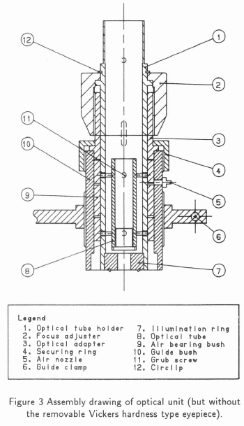
The principle used for the focusing of the optical unit was based on keeping the two lenses a fixed distance apart. This enabled hole depths to be measured by focusing on the top and then the bottom of the hole and reading the distance the optical tube holder (item 1) had moved, from measurement engravings on the optical adapter (item 3).
The drilling unit
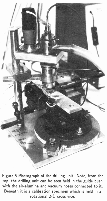
The item numbers given in this section refer to the design drawing shown in Figure 4. The drilling unit consisted of many small components with close tolerances so that consistently well drilled holes could be produced. A photograph of the designed drilling unit is shown in Figure 5.
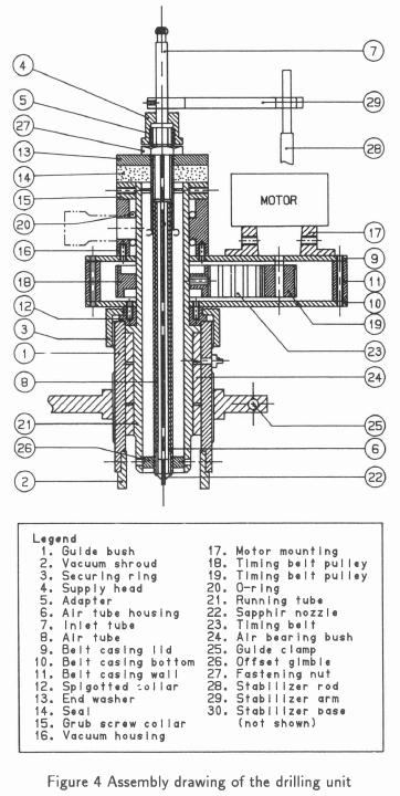
In order to achieve the required hole, as described earlier, the drilling unit was designed with an inlet tube (item 7) through which the air-alumina stream entered, an air tube (item 8) through which the air-alumina stream passed, and a 0.46 mm sapphire nozzle (item 22 - imported from SS White Industries in the USA - part number 353-1942x). Nozzle offset screws were provided in the offset gimble (item 26) to achieve the required hole diameter. Tilt adjustment screws were provided in the grub screw collar (item 15) to vary the nozzle tilt. A motor (2.4 V, 24 rpm) pulley system (items 18, 19 and 23) rotated the running tube (item 21), and thus the nozzle (item 22). In order to prevent the inlet tube from rotating, and thus the air-alumina supply hose from becoming twisted and entangled, a stabilising unit (items 28, 29, and 30) was designed.
Vacuum extraction of debris and alumina particles in the work area was achieved by placing the vacuum shroud, (item 2) over the work surface and connecting a domestic vacuum cleaner to the vacuum outlet tube. Debris was sucked from the work surface, and passed between the running tube (item 21) and the air tube housing (item 6) and through the vacuum holes in the running tube (item 21). The vacuum housing (item 16) had two O-rings (item 20) on its inside. These created a seal between the running tube (item 21) and the vacuum housing (item 16) so that ideally no abrasive particles were able to come into contact with moving parts.
A seal was created on top of the running tube by placing a neoprene seal (item 14) over the opening and clamping it down with an end washer (item 13), which was secured with a fastening nut (item 27).
Guide bush fixture and stand
The item numbers given in this section refer to Figure 4. The guide bush fixture and stand can also be seen in Figure 5. The guide bush was an extremely important feature of the unit. It remained in a fixed position providing a universal bush fixture for both the optical and drilling units, so that any specimen could be carefully aligned before drilling.
The guide bush (item 1) incorporated an air bearing (item 24) and had a bayonet fitting machined in it to hold the vacuum shroud (item 2) . Both the optical and drilling units f itted in it and were secured by a securing ring (item 3). The air bearing was employed solely for the optical unit, so that the optical unit could be accurately centered in it, with air being supplied through the copper nozzle in its side. When using the drilling unit, a light coat of oil was applied to the drilling unit so that there was lubrication between the metal contact surfaces.
The guide bush fixture was screwed into a guide clamp (item 25) to enable fine height adjustments of the drilling unit to be made, thus facilitating a nozzle tip to work surface distance of 1.5 mm. The guide clamp in turn was able to be moved vertically by the stand arrangement (see Figure 5) for coarse height adjustments.
The pneumatic circuit and alumina supply
Compressed air was obtained from a compressor at 6 bar, and was passed into an SS White Airbrasive model K54 machine, where it was regulated to 5.5 bar. The SS White Airbrasive machine fed alumina particles into the air stream by means of a mixing chamber (similar to an inverted salt shaker) mounted on a vibrator, which could be controlled. The air-alumina stream then entered the drilling unit through a hose attached to the inlet tube (item 7 of Figure 4). The air supply to the air bearing (item 24 of Figure 4) was tapped off from the pneumatic circuit, before the SS White machine
Calibration of the drilling unit
Before the experimental programme could be undertaken and even though the equation constants 1/K1 and vK2/K1are specified,26,31 calibration of the drilling unit facility was required. This calibration was undertaken primarily to check on hole geometries and centering, and also to compare stresses inferred from the residual stress AACH strain gauge rosettes with directly applied stresses.
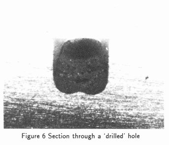
With respect to the 'drilled' hole geometries, the combination of offset and tilt capability were such that entirely normal or 'vertical' holes, perpendicular to the surface, could be drilled. A cross-section of such a drilled hole is shown in Figure 6, which shows the hole to be vertically sided.
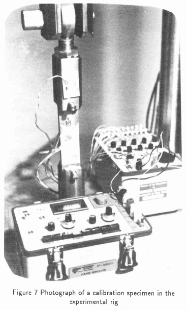
For the stress calibration aspect, a rectangular specimen was prepared and strain gauged so that it could be loaded in simple tension. The reason for this being that the equation constants conveniently reduce to simple expressions, as shown in equations (3) and (4), when considering a uniaxial stress field. Since it was not known whether any residual stresses were present in the calibration specimen to start with, the following previously accepted method6,30,32,35,45 was followed:
1. An aluminium bar was loaded axially to various known load levels within the elastic limit using a servohydraulic testing machine. (Stresses needed to be kept below 0.3σy in order to prevent plasticity effects due to the hole which was to be drilled.) The corresponding strains under these loads were recorded.
2. The specimen was unloaded and holes were drilled in the centre of the attached strain gauge rosettes.
3. The calibration specimen was located back in the servohydraulic test rig, the strain gauge readings were reset to zero and the specimen was reloaded to the previous load levels with the corresponding strains again being recorded.
4. The relaxed strains were calculated by subtracting the strains obtained in step 3 from those obtained in step 1.
By using this method, illustrated in Figure 7, any inherent residual stresses in the calibration specimen, such as rolled in stresses, were effectively cancelled out.
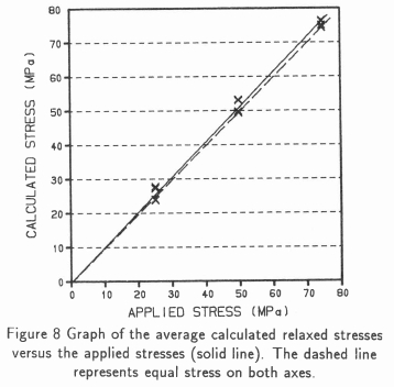
From the results obtained, 1/K1and vK2/K1compared favourably to their documented values. The relaxed stresses were rederived from the relaxed strains and compared to their applied values by plotting a calibration curve of measured versus applied stress. This is illustrated in Figure 8, where it can be seen that an acceptably close correlation using this technique was achieved. From these comparisons, it was found that the technique could be used with a 95% confidence level.53
Application of the AACH drilling texhnique
A situation where residual stress was believed to be playing a role was in the service performance of rods used in the mining industry for surface drilling exploration work.55 The basic rod was extruded from a billet into a seamless tubular section and subsequently straightened and heat treated. For service these rods are made up by manufacturing standard taper pipe threads on the inner diameter at both ends of the rods. Steel fittings were coupled to the ends of the rods, and tightened to a specified torque.55
As part of a rod quality assurance programme, mechanical tensile tests and compositional analysis of the alloy were undertaken. The microstructure was also examined and finally linear elastic fracture toughness tests carried out.56 The results of the mechanical, compositional and fracture toughness tests showed that the rods were indeed within specification55 from these points of view. Microstructural tests indicated that there were no unusual inclusions or phases in the material that may have been detrimental to the rods, properties55 or performance, but there was some limited evidence of environmentally assisted fatigue at the root of the first thread.55
If the rods were indeed susceptible to environmentally assisted cracking in the vicinity of the sharply machined threads, then the source of stress to initiate such crack development required investigation. The question that needed to,be answered was ... what had initiated crack growth? There were two possible suggestions: (i) the over-torque of the steel fittings (which was a problem that had been known to occur in the field), and (ii) the presence of significant residual stresses.57 In view of this latter issue, a research project was undertaken to measure residual stress of drill rods as a function of processing route. This paper addresses this question using the AACH drilling technique.
Experimental details
In this investigation three rods were considered for evaluation from a series supplied, Each rod was manufactured by a similar but slightly different proprietary manufacturing and heat treatment route. These routes were termed the 'old route' (rod A), which was the original manufacturing route used; the 'stretch route' (rod E), which differed from the 'old route' in that the straightening process was performed by means of a simple stretch as opposed to passing the rods through a series of reels oriented in a 3-D fashion; and the 'new route' (rod F), which differed from the 'old route' in the order of the sequential processes
The experimental procedure considered an initial geometric evaluation of the rods, followed by AACH drilling to measure the residual stresses predominantly on the outside surfaces of the rods, but also on their inside surfaces and at mid-wall thickness locations. Thereafter, various rods specimens were subjected to ring splitting residual stress measurements, which involved splitting the specimens through their wall thicknesses.21 By measuring the change in outer diameter, the average residual hoop stresses were calculated in the rod specimens. These ring splitting measurements were conducted in order to compare the results of a relatively simple (if slightly less accurate) technique well suited to shop floor applications, to the more precise one.
Results and Discussion
(i) Geometric evaluation
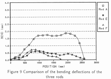
From the geometric evaluation it was found that all three rods had an initial bending deflection (curvature), somewhat similar to an arched bow - Figure 9. Rod F had been cut short, but if its full length had been received, then it appears that it would have a similar curvature to rods A and E, with two points of local maxima. It was not surprising that rod E had the smallest amount of curvature, since it had been straightened by a simple stretch process slightly in excess of its 0.2% proof stress. Rod F, which had been passed through the straightening reels on two different occasions (as opposed to once for rod A), appeared to have a smaller curvature than rod A, presumably for this reason.
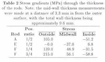
(ii) Residual stress measurements
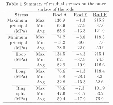
The main results which were found are summarised in Tables 1 and 2.53 It should be noted that a careful error analysis was undertaken53 on approved lines,26,32 which indicated that an error in residual stress of typically up to 6.2% could be expected. It can be seen from Tables 1 and 2 that rod F ('new route') had the highest measured residual stresses and that the residual stresses in rod E varied from compressive on the outside to slightly tensile on the inside, in contrast to rods A and F. It was also found that the maximum principal stresses in rods A and F generally acted in the hoop (or circumferential) direction of the drill rods, as expected from the extrusion and subsequent drawing processes; whereas in the case of rod E, the stresses were randomly oriented and distributed in an approximately equi-biaxial fashion. In Table 1, the average refers to the mean of four readings taken around the circumference, at a section.
The drill rods were divided into specimen lengths of 70 mm. To facilitate angular orientation, a clock face analogy was considered when viewing the rods end on, with the 12 o'clock position at the top of their curvature and the 6 o'clock position at the bottom. The maximum principal residual stresses measured on the outside surf ace of rods A and F and the maximum compressive residual stresses measured on the outside surface of rod E, are plotted as a function of distance along the length of the drill rods at the 12, 3, 6, and 9 o'clock positions, as shown in Figures 10-12.
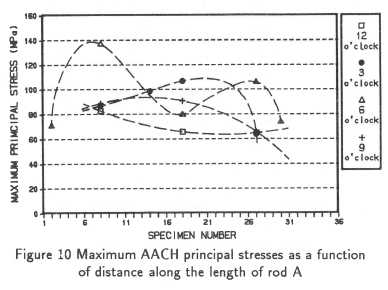
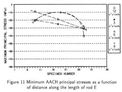
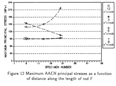
As can be seen, the maximum stresses in rods A and F tended to exist at the 6 o'clock position, while the maximum compressive stresses in rod E were effectively randomly distributed - again consistent with the randomly oriented, nominally equi-biaxial stress fields previously observed. It was hypothesised that the reason for the trend of the maximum residual stresses occurring at the 6 o'clock positions in rods A and F, was due to straightening. Since the rods were obviously more bent before straightening than after, the superimposed straightening stresses would be tensile at the 6 o'clock position and compressive at the 12 o'clock position. This hypothesis was further substantiated by noting that the stresses in rod F were higher than in rod A, and that rod F had been straightened more than rod A.
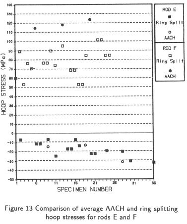
The ring splitting results showed that, although the residual stress results were lower than in the AACH drilling case, similar trends in the residual stress distributions were measured. In fact further comparison between the results yielded from the two techniques, showed that the ring splitting hoop stress results were a factor of typically 75% of the outer surface residual hoop stress results measured with the AACH drilling technique, with a variance of approximately 14%, as illustrated in Figure 13.
(iii) Contribution of residual stress to service performance
The question of whether residual stress plays any significant part in service performance needed to be addressed. Problems were experienced with rods manufactured according to the so called 'old route', therefore the results of rod A are examined here. Some high residual stresses were indeed measured in rod A, for example 137 MPa in specimen 8A at the 6 o'clock positions. However, on average the stresses were much lower - see Table 1 - and it would depend on the service loads whether these stresses are regarded as unacceptably high. It had been reported that environmentally assisted crack growth (corrosion fatigue but not stress corrosion cracking (SCC)) had occurred at the first engaged thread of some drill rods,55 which was near the centre of the rod wall thickness. If the stress gradient of rod A was considered, it could be reasoned that the stresses in this area are low. However it is not known how the machining of the thread at the end of the drill rods affected the residual stress distribution, since no threaded samples were examined. In addition the measured residual stresses were predominantly in the hoop direction yet there was no evidence of any longitudinal crack development. It was thus considered, from the physical evidence, that such problems that had occurred were more probably due to the threaded couplers (which connect the drill rods) being over-torqued,55 or bad handling aspects, rather than excessively high residual stresses due to manufacture. This had created a perception of rods being unacceptable, and this perception had turned out to be false. Indeed, if there were to have been consistently high residual stresses contributing to pipe cracking, the problem would have been generic, with vast numbers of pipe failures (from SCC) and this was not the case! Indeed pipe failures were remarkably rare.55
Nonetheless it was evident from this study that the 'stretch route' provided an improved manufacturing route, even though the stretch may be expensive to incorporate into the production line process. The advantages of the stretch route were that the induced residual stress appeared to be low and compressive which is advantageous from a service viewpoint.
Concluding remarks
An air abrasive centre hole drilling device was designed and built, based on a similar system due to Beaney and Procter.26,31 It could be used as an accurate and reliable method of residual stress measurement and was used tc measure residual stress values within an accuracy of approximately 6%. The AACH as well as the simpler ring splitting techniques were both used to perform residual stress measurements on sample (7075-T6) rods used in the mining industry.
For these rods, the highest residual stresses were found on the outer surfaces of the 'new route' processed rod (rod F), followed by the 'old route' processed rod (rod A), with tensile values of 215 and 137 MPa, respectively. The 'stretch route' processed rod (rod E), exhibited the lowest residual stresses and these were opposite in sign (i.e. compressive) with a maximum compressive value of -39.6 MPa. Furthermore, stress reversal existed through the wall thickness of the rods, with a 'maximum' inside surface stress value of -51.3 MPa, 6.8 MPa, and -58.8 MPa for rods A, E, and F, respectively. For rods A and F, the first principal stress was aligned predominantly in the hoop or circumferential direction; whereas for rod E, stresses acted more biaxially, or in effectively randomly distributed directions.
The residual stresses measured using the ring splitting technique compared well with, and followed the trends exhibited by, the AACH drilling results. However, being a through thickness average rather than a measure of localised surface stress, they were lower in magnitude - typically 75%. Although the rod sampling was limited, it was considered, from the residual stress tests undertaken, that residual stress effects did not and do not play a significant role in inhibiting service performance of the rods.
References
[1] Johnson W & Mellor PB. Plasticity for Mechanical Engineers. D. Van Nostrandt Company Ltd, London, 1962, pp.206-208.
[2] Perry CC. Residual Stress ... the Nemesis of the Liberty Bell. Epsilonics, 1983; 10-11.
[3] Polakowski NH. Strength and Structure of Engineering Materials. New Jersey, 1966, pp.458-484.
[4] Masubuchi K. Analysis of Welded Structures. Pergamon Press, Great Britain, 1980, pp.112-136.
[5] Mathar J. Determination of Internal Stresses by Measuring the Deformation Around a Drilled Hole. Transactions of the American Society of Mechanical Engineers, 1934, 56, 249-254. [ Links ]
[6] Soete W & Vancrombrugge R. An Industrial Method for the Determination of Residual Stresses. Proceedings of the Society of Experimental Stress Analysis, 1950, 8, 17-28. [ Links ]
[7] Niku-Lari A, Lu J & Flavenot JF. Measurement of Residual Stress Distribution by the Incremental Hole-Drilling Method. Experimental Mechanics, 1985, 25, 175-185. [ Links ]
[8] Throop JF. Fracture Mechanics Analysis of the Effects of Residual Stress on Fatigue Life. ASTM Journal of Testing and Evaluation, 1983, 75-78.
[9] Nawwar AM & Shewchuk J. The Effect of Preload on Fatigue Strength of Residually Stressed Specimens. Experimental Mechanics, 1983, 23, 409-413. [ Links ]
[10] Wilks MDB, Nowell D & Hills DA. The Influence of Residual Stress on Crack Growth Rate. Proceedings of the Fourth SEM International Conference on Residual Stresses, 1994, 1238-1245.
[11] Ragozin YI & Polianin IV. A New Express Method of Residual Stress Relief in Metals and Ceramics. Proceedings of the Fourth SEM International Conference on Residual Stresses, 1994, 926-931.
[12] Nakagiri A, et al. The Residual Stress Relief Under Mechanical Vibrations and Subsequent Dimensional Change in Copper and Brass. Proceedings of the Fourth SEM International Conference on Residual Stresses, 1994, 23, 1300-1305. [ Links ]
[13] Peck CA. Practical Aspects of Residual Stress Measurement by X-Ray Diffraction. Proceedings of ASM Conference on Residual Stress in Design, Process and Material Selection, 1987, 7-9.
[14] Cohen JB. The Non-Destructive Measurement of Residual Stresses Via Diffraction. Proceedings of the Fourth SEM International Conference on Residual Stresses, 1994, 1 - 13.
[15] Prask HJ & Choi CS. Residual Stress Measurements in Armament System Components by Means of Neutron Diffraction. Proceedings of ASM Conference on Residual Stress in Design, Process and Material Selection, 1987, 21-26.
[16] Smith DJ, et al Neutron Diffraction Measurements of Residual Stress and Plastic Deformation in an Aluminium Alloy Weld. Journal of Strain Analysis, 1988, 23, 201-211. [ Links ]
[17] Wobker HG, Karpuschowski B & Regent C. Quality Control of Residual Stresses on Ground Workpieces with Micromagnetic Techniques. Proceedings of the Fourth SEM International Conference on Residual Stresses, 1994, 424-433.
[18] Ruud CO, DiMascio PS k Yavelak JJ. Comparison of Three Residual Stress Measurement Methods on a Mild Steel Bar. Experimental Mechanics, 1985, 25, 338-343. [ Links ]
[19] Bruce Thompson R. An Overview of Ultrasonic Measurement Techniques. Proceedings of the Fourth SEM International Conference on Residual Stresses, 1994, 97-111.
[20] Tokarcik AG & Polzin MH. Quantitative Evaluation of Residual Stresses by the Stress Coat Drilling Technique. Experimental Stress Analysis, 1952, 9, 195-207. [ Links ]
[21] Sachs G & Espey G. The Measurement of Residual Stresses in Metals. The Iron Age, 1941, 63-71.
[22] Witt F, Lee F & Rider W. A Comparison of Residual Stress Measurements Using Blind Hole, Abrasive Jet and Trepan-Ring Methods. Experimental Techniques, 1983, 7, 41-44. [ Links ]
[23] Misra A & Peterson RA. Examination of the Ring Method for Determination of Residual Stress. Experimental Mechanics, 1981, 21, 268-272. [ Links ]
[24] Procter E, Beaney EM & Mitchell DH. Deep Hole Residual Stress Measurement. Short Course on Residual Stress Measurement, Strain Society of South Africa, 24 November 1987.
[25] Cheng W & Finnie I. An Overview of the Crack Compliance Method for Residual Stress Measurement. Proceedings of the Fourth SEM International Conference on Residual Stresses, 1994, 449-458.
[26] Beaney E M. Accurate Measurements of Residual Stress on any Steel Using the Centre Hole Method. Strain, 1976, 12, 99-106. [ Links ]
[27] Rendler NJ & Vigness I. Hole Drilling Strain Gage Method of Measuring Residual Stresses. Experimental Mechanics, 1966, 6, 577-586. [ Links ]
[28] Flaman MT. Brief Investigation of Induced Drilling Stresses in the Centre-Hole Method of Residual-Stress Measurement. Experimental Mechanics, 1982, 22, 26-30. [ Links ]
[29] Bush AJ & Kromer FJ. Simplification of the Hole-Drilling Method of Residual Stress Measurement. ISA Transactions, 1973, 12, 249-259. [ Links ]
[30] Bynum JE. Modifications to the Hole Drilling Technique of Measuring Residual Stresses for Improved Accuracy and Reliability. Experimental Mechanics, 1981, 21, 21-33. [ Links ]
[31] Beaney EM. Instuction Manual for the CEGB Air Abrasive System for Measuring Residual Stresses, 1986.
[32] Beaney EM & Procter E. A Critical Evaluation of the Centre Hole Technique for the Measurement of Residual Stresses. Strain, 1974, 7-14.
[33] Schajer G S. Measurement of Non-uniform Residual Stress Using the Hole Drilling Method. Part I - Stress Calculation Procedures. ASME Journal of Engineering Materials and Technology, 1988, 110, 338-342. [ Links ]
[34] Bathgate RG. Measurement of Non-Uniform Bi-Axial Stresses by the Hole Drilling Method. Strain, 1968, 4, 20-29. [ Links ]
[35] Kelsey RA. Measuring Non-uniform Residual Stresses by the Hole Drilling Method. Proceedings of the Society for Experimental Stress Analysis, 1956, 14, 181-194. [ Links ]
[36] Ruud CO, DiMascio PS & Yavelak JJ. Comparison of Three Residual Stress Measurement Methods on a Mild Steel Bar. Experimental Mechanics, 1985, 25, 338-343. [ Links ]
[37] American Society for Testing and Materials. Standard Test Method for Determining Residual Stresses by the Hole-Drilling Strain-Gage Method. ASTM Standard E837-89, 1989.
[38] Tootoonian M & Schajer GS. Enhanced Sensitivity Residual Stress Measurements Using Taper Hole Drilling. Proceedings of the Fourth SEM International Conference on Residual Stresses, 1994, 52-62.
[39] Timoshenko SP & Goodier JN. Theory of Elasticity. 2nd edn. McGraw-Hill, New York, 1951, p.80.
[40] Schajer GS. Application of Finite Element Calculations to Residual Stress Measurements. ASME Journal of Engineering Materials and Technology, 1981, 103, 157-163. [ Links ]
[41] Gupta BP. Hole Drilling Technique: Modifications in the Analysis of Residual Stresses. Experimental Mechanics, 1973, 13, 45-48. [ Links ]
[42] Wang J. Measurement of Residual Stress by the Hole Drilling Method: on the Direction of Maximum Residual Stress. Experimental Mechanics, 1988, 28, 24-26. [ Links ]
[43] Wang J. Measurement of Residual Stress by the Hole Drilling Method: General Stress-Strain Relationship and its Solution. Experimental Mechanics, 1988, 28, 355-358. [ Links ]
[44] Flaman MT & Boag JM. Comparison of Residual Stress variation with Depth Analysis Techniques for the Hole Drilling Method. Experimental Mechanics, 1990, 30, 352-355. [ Links ]
[45] Lu J & Flavenot JF. Applications of the Incremental Hole Drilling Method for Measurement of Residual Stress Distribution. Experimental Techniques, 1989, 13, 18-24. [ Links ]
[46] Flaman MT & Manning BH. Determination of Residual Stress Variation with Depth by the Hole Drilling Method. Experimental Mechanics, 1985, 25, 205-207. [ Links ]
[47] Flaman MT, Mills BE & Boag JM. Analysis of Stress Variation with Depth Measurement Procedures for the Centre Hole Method of Residual Stress Measurement. Experimental Techniques, 1987, 11, 35-37. [ Links ]
[48] Shaw D & Chen HY. A Finite Element Technique to Analyze the Data Measured by the Hole Drilling Method. Experimental Mechanics, 1990, 30, 120-123. [ Links ]
[49] Nickola WE. Practical Subsurface Residual Stress Evaluation by the Hole-Drilling Method. Proceedings of the Spring Conference on Experimental Mechanics, 1986, 47-58.
[50] Schajer GS. Measurement of Non-Uniform Residual Stresses Using the Hole Drilling Method. Part II - Practical Application of the Integral Method. ASME Journal of Engineering Materials and Technology, 1988, 110, 344-349. [ Links ]
[51] Bijak-Zochowski M.A Semi-Destructive Method of Measuring Residual Stresses. VDI-Berichte, 1978, 313, 469-476. [ Links ]
[52] Kabiri M. Towards More Accurate Residual Stress Measurement by the Hole Drilling Method: Analysis of Relieved-Strain Coefficients. Experimental Mechanics, 1986, 26, 14-21. [ Links ]
[53] Segal AM. Residual Stress Evaluation of Aluminium Drill Rods. Master's thesis, University of Cape Town, 1995. [ Links ]
[54] S S White. Industrial Abrasive Unit Model K - Service Manual.
[55] Harty BD. Technical Assistance Report No. HTA 90/10 CT. Hulett Aluminium Internal Report, May 1990.
[56] Tait RB. LEFM Fracture Toughness Measurement of 7075 Aluminium Alloy Drill Rod Materials. Department of Mechanical Engineering, University of Cape Town, April 1991.
[57] Tait RB. Failure of 7075 Drill Rods - Review of Report HTA 90/10 May 1990. Department of Mechanical Engineering, University of Cape Town, June 1990.
Received May 1995
Final version February 1996
