




Services on Demand
Journal

Article
 English (pdf)
 Article in xml format
 Article references

 Automatic translation
 Send this article by e-mail
Indicators
Related links
-
 Cited by Google
-
 Similars in Google
Share

 Permalink

R&D Journal
On-line version ISSN 2309-8988Print version ISSN 0257-9669
R&D j. (Matieland, Online) vol.12 Stellenbosch, Cape Town 1996
Simplified thin-ship theory with application to the design of bulbous bows
G.D. ThiartI; P.D. DamantII
ISenior Lecturer, Department of Mechanical Engineering, University of Stellenbosch, Private Bag XI, Matieland, 7602 South Africa
IIGraduate, Department of Mechanical Engineering, University of Stellenbosch
ABSTRACT
A method for calculating the wave resistance of a ship by means of so-called Kelvin 'wavemaking' source panels on the centreplane of the ship is described. The method is a simplification of conventional thin-ship theory, which involves complicated Fourier expansions and which is very difficult to apply for hull forms other than those which can be described by simple analytical functions. A computer program to calculate wave resistance by means of this simplified theory was developed and used to calculate the wave resistance of a 24 m purse seine trawler. Results are presented for the trawler with and without a bulbous bow, at design speed and for two operating conditions. Fair correspondence between the prediction of the reduction in effective power requirement by means of the theory and by means of towing tank model tests was obtained.
Nomenclature
Introduction
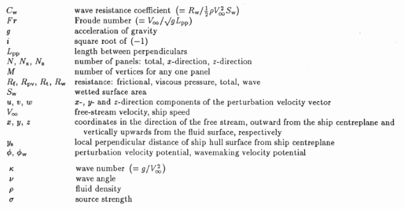
The total resistance of a ship can be subdivided into three parts,[1] i.e. the skin friction resistance Rf, the viscous pressure resistance Rpv (due to separation of the flow at the stern of the ship resulting in incomplete pressure recovery) and the wave resistance Rw (due to the continual supply of energy necessary to maintain the wave system that spreads out behind the ship):

Arguably the simplest method for reducing the resistance, and hence the effective power requirement, of a given displacement ship with given operating conditions, is the addition of a bulbous bow. Kracht [2] divides the effect of the bulbous bow into two categories, i.e. (1) the interference effect and (2) the breaking effect. The interference effect refers to the interference between the free wave system of the ship and the waves generated by the bulbous bow itself, the geometry of which can be 'tuned' to cause partial cancellation of the ship wave system at normal operating conditions. The breaking effect refers to the attenuation of the bow wave system by improving the flow around the forebody and thus preventing the breaking of the bow waves. Thus the purpose of the bulbous bow is mainly to reduce the wave resistance, which can vary between about 15% of total resistance for a cargo vessel at low speed to about 60% for a destroyer at high speed.[3]
The purpose of this paper is to present a method for the calculation of wave resistance for displacement ships that is easy to apply and which yields reliable results for affordable work input. Such a method is essential for the initial design of a bulbous bow for a given ship.
Mathematical model
Various methods are available for calculating the flow around a ship hull, ranging from full Navier-Stokes solutions with turbulence modelling (see for example Larsson et al. [4]) through panel method potential flow solutions using panels distributed over the surface of the ship (see for example Jensen et al. [5]) to thin-ship theory which yields a potential flow solution for the flow around a ship in a similar fashion to that of thin airfoil theory for the flow around an airfoil. Both the Navier-Stokes and the full potential flow options require huge amounts of computational time, and are at present only used to compare two or three design options. For the purpose of initial design, thin-ship theory is more cost-effective: although most displacement ships cannot be considered as thin, the theory yields reasonable approximations of the differences between the wave resistances of various modified versions of the same basic ship.[6]
Michell [7] developed the theory of thin ships moving with a uniform velocity V∞into still water almost a century ago. The mathematical problem is to find the solution to Laplace's equation for the perturbation velocity potential,

subject to the following boundary conditions:
1. The linearized no-throughflow boundary condition on the ship hull:

2. The linearized free surface boundary condition:

3. The radiation condition, i.e. that the free surface far ahead of the ship must remain undisturbed:

4. The bottom condition, i.e. that the fluid far below the ship must remain undisturbed:

Once the velocity potential has been found, the wave resistance of the ship can be obtained from the wake integral:[1]

The subscript oo in Eq. (7) indicates that the perturbation velocities have to be calculated at an yz-plane at a distance very far astern of the ship.
Michell [7] used a Fourier expansion to arrive at the expression for the velocity potential. The resulting expression for the wave resistance of a ship is in the form of the sum of two triple integrals and one quadruple integral. Although the quadruple integral and one of the triple integrals vanish through symmetry, the mathematics involved in calculating the resistance by this means is very complicated, even for hull forms that can be described by simple mathematical functions.
A simpler solution method is that of representing the ship by means of Kelvin wave-making sources (see for example Gadd [8]) on the centreplane of the ship, i.e. on the zz-plane at y = 0. The velocity potential associated with a Kelvin source of strength a located at x = a, y = 0, z = - c (where c is a positive number) consists of three parts: the velocity potential of a Rankine source of strength σ located at x = a, y = 0, z = -c, the velocity potential of its image located at x = a, y = 0, z = c, and a wavemaking part given in complex notation by
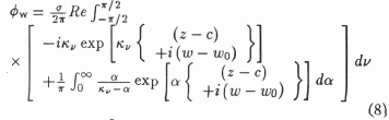
where ku = ksec2*/, w = x cos v + y sin v, w0 - a cosv, v is the angle between the direction of propagation of a wave and the free stream direction and α is a parameter of integration.
These Kelvin sources satisfy Laplace's equation, as well as the linearized free surface condition, the radiation condition and the bottom condition. A Kelvin source therefore represents a solution for a source-type flow in the presence of a free surface. The velocity potential for a ship represented by a source distribution σ(x,0,z) on its centreplane is obtained by replacing φw and σin Eq. (8) with dφw and σdS, respectively, and integrating over the area of the centreplane. The source strength required at a certain point is determined by the no-throughflow boundary condition on the ship hull. Karamcheti [9] gives the corresponding magnitude of the required source distribution for a thin airfoil, which can be shown to hold also for a thin ship, as

Instead of using a continuously varying source distribution, the problem is simplified by dividing the centre-plane area into a number of M-sided panels, on each of which the source distribution is assumed to be constant (equal to its value at the geometrical centre of the panel). The value of M can be different for all panels, but usually triangular and quadrilateral panels are sufficient. It can be shown that the wavemaking velocity potential due to such a panel with constant source strength per unit area that is obtained by integrating Eq. (8) over the panel, is given by
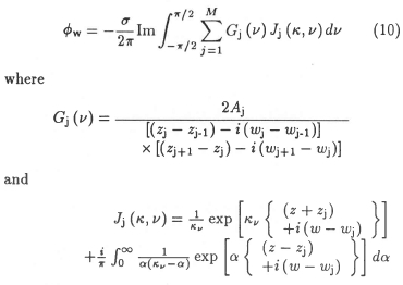
Here Ajis the area of the triangle formed by the vertices (j - 1) , (j) and (j + 1), and Wj= Xjcos v. Note that - 1 is defined as M for j = 1, and that j + 1 is defined as 1 for j = M.
The wavemaking velocity field which is induced by the submerged panel is obtained in the usual manner by differentiating Eq. (10). The resulting expressions for the perturbation velocity components very far astern of the ship due to N panels are given by
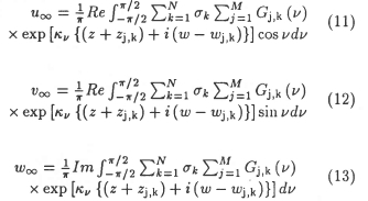
The expression for the wave resistance of the ship hull as represented by the panels of constant source strength is obtained by substituting Eqs. (11)-(13) into Eq. (7). The result is as follows:
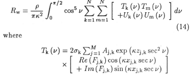
and
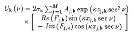
The function Fj,k is the even part (with respect to V = 0) of Gj,k (v)/2Aj,k and is defined by the expression
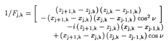
Full details of the derivation of Eqs. (10)-(14) are given by Damant [10] for the specific case of quadrilateral panels.
Computer program
A Fortran computer program was developed for the calculation of wave resistance by means of Eq. (14) using triangular and quadrilateral panels. In the program, the integral in Eq. (14) is evaluated numerically by means of Gaussian quadrature, using 64 Gauss points (results generally differed by less than half a percent if 32 Gauss points were used). All the results reported here were calculated in double precision on the University of Stellenbosch VAX ALPHA 3000-800.
Several case studies were undertaken to verify that the program was working correctly. One of these was the calculation of the wave resistance of the hull form used by Michell [7] in his original paper. This hull form is defined by the expression
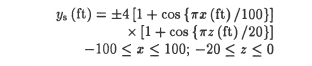
where the origin of the coordinate axis is at the intersection of the vertical median plane, the midship plane and the plane of the undisturbed water surface. The projection of the hull surface on the centreplane is rectangular, and therefore the hull surface was divided into Nx × NZ) rectangular panels for the computations described here. Panels were concentrated near the free surface, as shown in Figure 1 for a 32 × 8 subdivision.

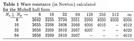
Results of the wave resistance calculations are shown in Table 1 for a ship speed of 20 ft/s, the same as that used by Michell in the one and only calculation reported in his paper. The value of ρwas taken as that of seawater, i.e. 1023 kg/m3, and the value of g as 9.807 m/s2. It is evident from Table 1 that grid-independent results are obtained for Nz = 32, but not for Nx. The values in the last column were found by means of Richardson extrapolation for a second order scheme, i.e. by estimating the error of the solution on the finest grid as one third of the difference between the solutions on the finest and second finest grids. It is evident that the wave resistance calculated by means of the proposed panel method is quite close to the 4181 N ('940 lbs. wt. about') calculated by Michell. The small difference that does exist can be ascribed to the difference between the two mathematical models. Slightly different values of water density and of g might also have been used by Michell in his calculation.
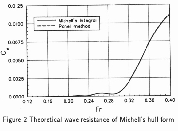
The wave resistance coefficient of Michell's hull form as function of Froude number, calculated by means of the proposed panel method with a 128 × 32 subdivision and using 64 Gauss points for the numerical integration, is compared in Figure 2 with the Michell integral results, which were obtained by means of the method described by Wigley.[11] The difference between the two sets of results is only discernible at the higher Froude numbers, where the panel method values are too large by approximately half a percent compared to the analytical results.
Utilization for bulbous bow evaluation
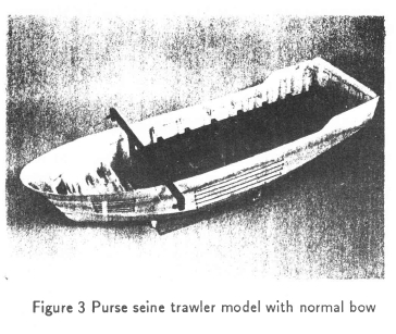
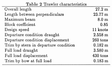
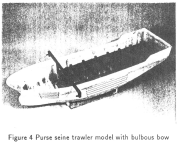
Damant [10] conducted towing tests in the University of Stellenbosch towing tank on the 1/15 scale model of a 24 m purse seine trawler shown in Figure 3. The main characteristics of the trawler are summarized in Table 2. The tests were carried out at the two predominant load conditions which are detailed in Table 2, using the model with a normal bow as shown in Figure 3, and also with a bulbous bow fitted as shown in Figure 4. The bulb has circular cross sections, and was designed by exploring a large number of options by means of the proposed thin-ship theory presented in this paper, taking guidance from the recommendations of Kracht [2] and Couch & Moss.[12] Measured differences in total resistance (∆Rt) are presented in Table 3 for Froude numbers in the range 0.34 to 0.44, which corresponds to the operating speed range of the trawler (10 to 13 knots).
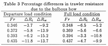
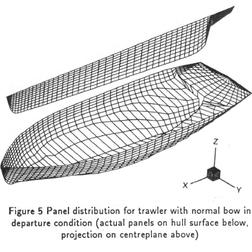
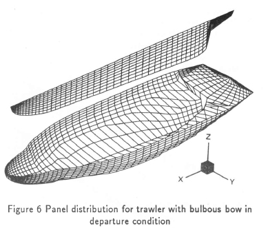
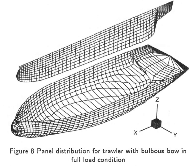
The differences in wave resistance due to the bulbous bow (∆RW) were also calculated by means of the proposed panel method. The results shown in Table 3 were obtained using 200 × 40 panel subdivisions similar to the 50 × 10 subdivisions shown in Figures 5 to 8. The results for the 200 × 40 subdivisions differed in general by less than half a percent from those using 100 × 20 subdivisions.

It is evident that the decrease in wave resistance predicted by the proposed theory is generally of the same order of magnitude as the experimentally determined decrease in total resistance. Unfortunately it is not possible to compare directly the decreases in wave resistance, because wave resistance alone cannot be determined experimentally by means of the force measurements.
Concluding Remarks
It has been shown that the panel method proposed in this paper for implementing classical thin-ship theory yields very accurate results when compared with analytical solutions of the same theory. The method also proved to give reasonably satisfying predictions for the bulbous bow effect, even though the ship for which calculations were done cannot be considered as thin. Further work that is envisaged is to implement the method in a design optimization program.
References
[1] Clayton BR & Bishop RED. Mechanics of marine vehicles, Spon, London, 1982.
[2] Kracht AM. Design of bulbous bows, SNAME Trans., 1978, 86, 197-217. [ Links ]
[3] Phillips-Birt D. Ship model testing, International Textbook Company Ltd., London, 1970.
[4] Larsson L, Broberg L, Kim KJ & Zhang DH. A method for resistance and flow prediction in ship design, SNAME Trans., 1990, 98, 495-535. [ Links ]
[5] Jensen G, Bertram V &Söding H. Ship wave-resistance computations, 5th Int. Conf. on Numerical Ship Hydrodynamics, 1989, Hiroshima.
[6] Wehausen JV. The wave resistance of ships, Adv. Appl. Mech., 1973, 13, 93-245. [ Links ]
[7] Michell JH. The wave resistance of a ship, Phil. Mag., 1898, 45, 106-123. [ Links ]
[8] Gadd GE. Ship wavemaking in theory and practice, RINA Trans., 1969, 111, 487-505. [ Links ]
[9] Karamcheti K. Principles of ideal-fluid aerodynamics, Wiley, New York, 1966.
[10] Damant P. Design of a bulbous bow by means of thin-ship theory, MEng thesis, University of Stellenbosch, 1994. [ Links ]
[11] Wigley WCS. Ship wave resistance: a comparison of mathematical theory with experimental research, INA Trans., 1926, 68, 124-141. [ Links ]
[12] Couch RB & Moss JL. Application of large protruding bulbs to ships of high block coefficients, SNAME Trans., 1966, 74, 392-441. [ Links ]
First received June 1995
Final version September 1995
